Unboxing the Gigabyte X99-UD4P Page 1
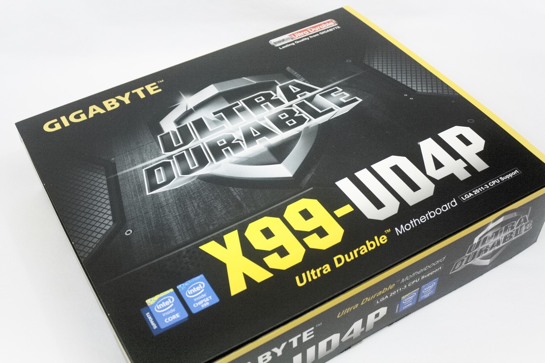
Now it is time for us to give the Gigabyte X99-UD4P a quick look over and see what comes with the motherboard and how Gigabyte packaged up this motherboard. Gigabyte, in typical fashion, gives us plenty of information about this motherboard on the outside of the box. Information pertaining to the fact that this is a X99 based platform, which supports Intel’s 2011v3 Core i7 series CPU’s, and that the X99-UD4P motherboard falls into Gigabyte’s Ultra Durable line of motherboards.
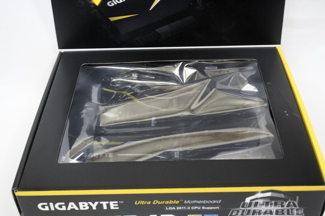
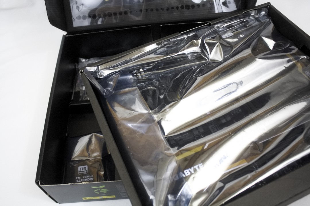
Opening up the lid of the box reveals the X99-UD4P motherboard wrapped in an anti-static bag.
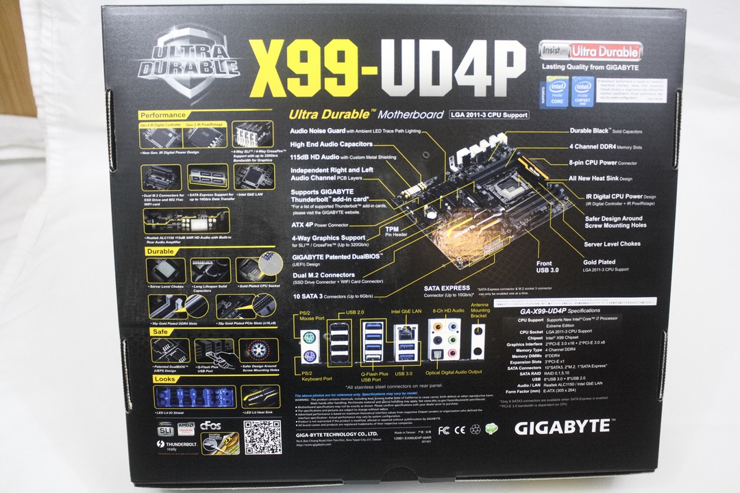
A quick glance on the bottom side of the motherboard box where Gigabyte has included a lot of information about the motherboard..

Gigabyte compartmentalizes the interior of the motherboard box, which in turn makes it easier for us to identify the individual included hardware items.
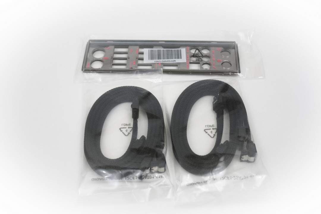
Here are some of the individual components that come included with the Gigabyte X99-UD4P motherboard. Gigabyte includes a light up I/O shield, and 4 SATA 6Gb/s cables that are sleeved.
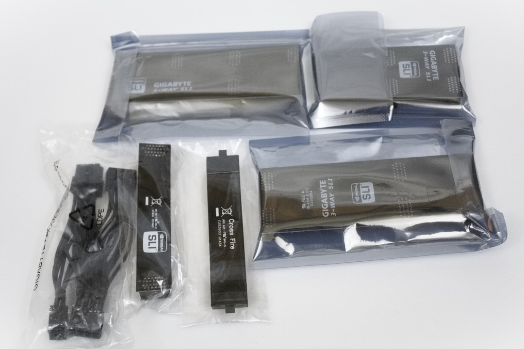
Gigabyte also includes 4 different Nvidia SLI bridges, and an AMD CrossFire bridge for when we feel the need to run with more than one video card. We are given a power adapter as well to be used if your PSU does not have enough 6-pin or 8-pin pci-power cables.
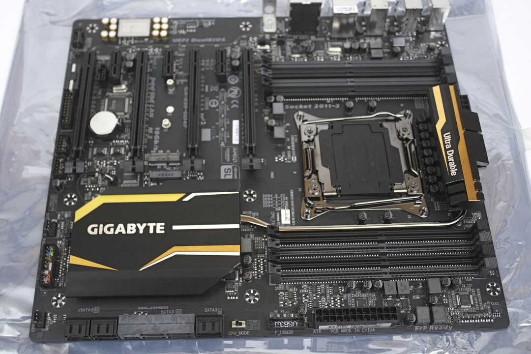
Now it is time for me to turn my attention over to the X99-UD4P motherboard. Upon first glance we can see that Gigabyte did a really nice job on the overall layout of this motherboard. The CPU socket area is open enough to use a plethora of different types of CPU coolers and the bolt holes are clear of any small electronic components. Gigabyte has utilized all of the available PCI expansion ports, instead of following the going trend of killing the upper PCI expansion port as I have seen on other motherboards. This is not an expanded ATX motherboard, it is indeed a standard sized ATX configuration motherboard with all 7 PCI Expansion ports available.
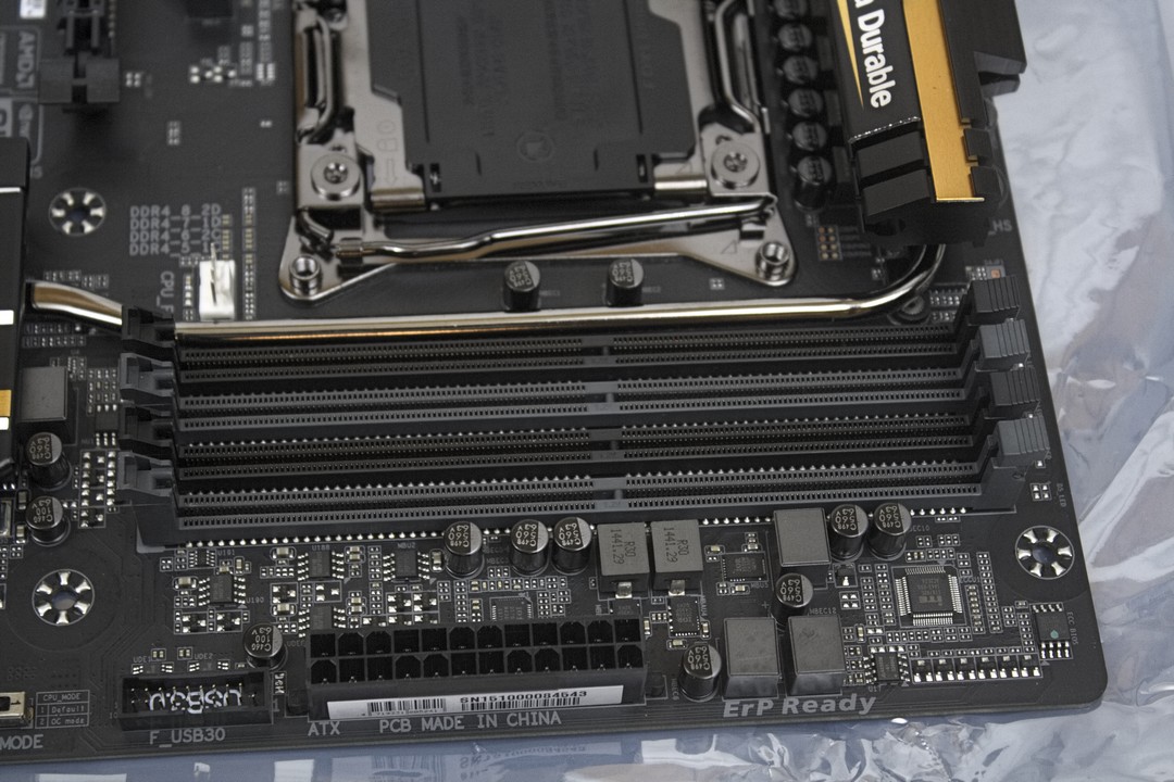
We are going to start on the corner closest to the main 24-pin power connector, then work our way around the motherboard. The Gigabyte X99-UD4P motherboard allows the use of eight DDR4 DIMMs, four of which are located near the main 24-pin power plug. If you look more closely to the memory slots, you will notice that on the left side of these there are no memory locks. The locks are only on the right side of the memory slots. This is nothing new, but I am glad to see more manufacturers utilizing this particular type of memory slot, as it makes it a lot easier to install or remove memory while a video card is in the primary PCI-E expansion port. To the left of the main 24-pin power plug is the front USB 3.0 header. Once again, I would like to mention how well the general area is cleaned up, everything has a place and it shouldn’t get in the way of us plugging in our power connectors, or securing the motherboard to our chassis.
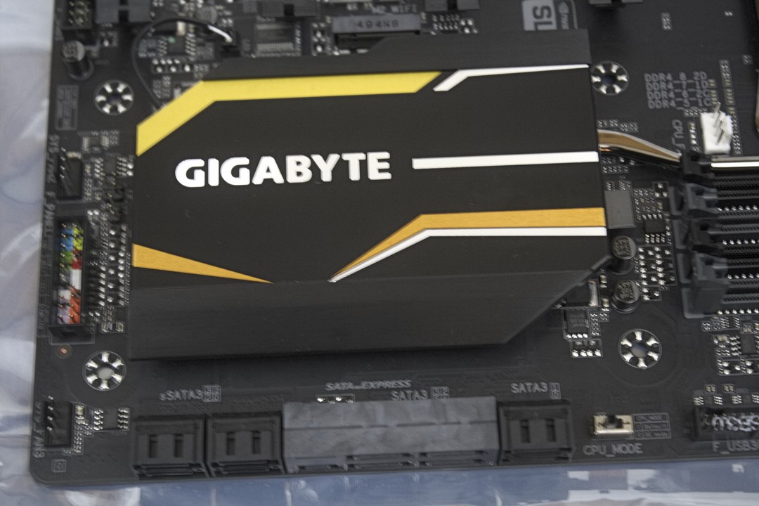
Moving to the left on the lower side of the X99-UD4P motherboard, we can see that Gigabyte uses a rather large heat sink on the PCH. Directly below this heat sink are the SATA 6Gb/s connectors and to the left of the heat sink near the bottom corner is a fan header, the front power/reset buttons, power/HDD activity LEDs, and front speaker I/O header. It is color coded to make things easier for us to hook up our switches, and activity LEDs. In the area just up from the front I/O header and towards the PCH heatsink is where the Clear CMOS header is located. Directly above the front I/O header is another fan connector.
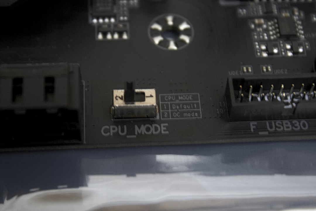
Located to the right of the SATA 6Gb/s storage expansion ports is a little switch labeled “CPU_MODE”. It comes set to “Default”, so if you plan on overclocking your CPU, this switch will have to be moved to position 2, “OC mode”.

Next we will be looking at the SATA 6Gb/s storage expansion ports a bit more closely. Starting from the right moving left, Gigabyte includes two standard SATA 6Gb/s connectors. To the left, we have two SATA Express connectors, that can be used in a standard SATA 6Gb/s configuration if you do not have a SATA Express storage device. These SATA Express ports are native to the PCH. To the immediate left are four more SATA 6Gb/s connectors, these are on another controller and are not native to the PCH. We should also mention that they only support IDE mode or AHCI modes and RAID is not supported.

Here we have a closer look at the Clear CMOS jumper, it is the first two frontal pins that are nestled in between the front I/O header and the PCH heatsink. Why Gigabyte chose to use a jumper instead of a button is beyond me. This jumper is also placed it in a difficult to reach location and does not include a jumper that is needed to clear the CMOS. I haven’t seen this type of setup since the old AMD Athlon days. Thankfully a metal object (ie. A small flat-bladed screw driver) touching the two pins will suffice enough to clear the CMOS if and when it is required, as we experienced a few times ourselves.


