This cool electronic light show is one of the easiest mods I’ve ever seen. The lights flash outward from the center when your hard drive is active. During heavy access, all the LED light up. This is a perfect ”beginner’s mod”.
Introduction
This nifty electronic light show is one of the prettiest and easiest mods I’ve ever seen. It’s like the bar graphs on your stereo, except the bar lights up during hard disk activity. The LEDs flash outward from the center when your hard drive is active. During heavy access, all the LEDs are lit. At other times, the bar is partly lit, and it’s completely dark when the drive(s) are not in use.
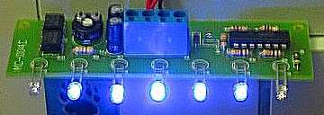
Oooh, look at the purty flashing lights…

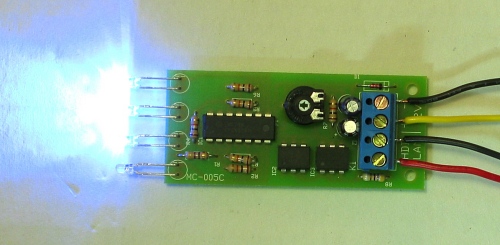
The 4 LED version has very bright LEDs too
There is also a 4 LED version of this kit. It lights up from one end instead of from the center. This shorter model would probably look best mounted vertically, perhaps as a pair of matching units on the left and right side of the case. The height is about right to fit vertically on a 5 1/4 drive bay cover. It’s possible to “gang” these units together for a larger, more elaborate multi-module mod.
Specifications & Features
Specifications: ( Straight from the insert that came with the box. )
Features:
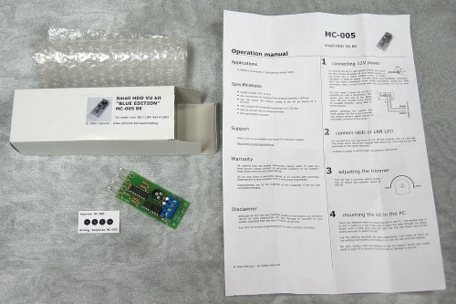
Package Contents:
Installation
Actually, since this is a mod, the ease / difficulty of installation is the most important factor in selecting a project. This mod is very easy. All you need to be able to do is cut and strip wires, drill holes in your case, and use a screwdriver. This is a great first-time mod. I had mine up and running (in a test configuration) in less than 15 minutes:

Notice how bright the LEDs are.
If you decide to install this mod, you might want to print out this section of the article (in Landscape mode), so that you can follow along, even if your computer is turned off. So that none of the text gets chopped off by the printer, please use the File / Page Setup command in your Web Browser (Internet Explorer) to set all 4 margins to 0.5 inches.
Tools Needed:
Optional Items
Disclaimer: Modifying your computer involves drilling holes in your case and working with the electrical system inside it. Even though this is a simple mod, you could possibly damage the computer or hurt yourself. Please be careful; Bjorn3d cannot be held responsible for any damage. If you are not certain you can install this mod by yourself, find someone who has experience working with electrical circuits, power tools, and preferably has previously modded a computer.
Step 1: Connect unit to power
Always turn the computer power off before performing any kind of electrical work on your PC. (If you are NOT using the optional molex extension cable, you will need to wire the unit directly to your power supply.)
The best way to connect this unit to your power supply is to use a molex extension cable. (Molex connectors are used to power hard drives, CD burners, DVD players, etc. and are standard equipment on PC power supplies.) By using a molex extension cable, that way you can easily disconnect your unit when the need arises. This is especially important when attaching an electrical mod to the front of a removable faceplate. Actually, the faceplate of my computer must be removed first, before the inside of the case can be accessed.
If you use any connector in a non-standard way, like Im doing here, its a good idea to clearly label the connector (so that you dont accidentally fry your computer when you are plugging equipment in).
Plug the extension cable into a power supply molex and cut off the other end (of the extension cable). Strip 3/8th of an inch (1 cm) of the plastic insulation from the end of each wire. For best results, you should use a wire stripper tool, but you can also carefully cut the plastic coating, leaving the metal wires untouched, and gently pull the plastic covering off. Some people even strip wires with their teeth, but that is NOT recommended!
Only 2 wires (the yellow and a black) are needed to power the unit, so you will need to shorten the red wire and one black wire (so they are not dangling inside your case) and then insulate the cut ends with wire nuts or black electrical tape. Also, if your power supply has a “fan bus” (like my Antec 430 True Power), be certain you connect the mod to a main power molex connector and not a fan bus connector.
Since the front of my computer is frequently removed, I used a second molex extension cable, so that I would have enough power cable to lay the front panel on the floor without actually having to disconnect the cables.
The two stripped wires should be inserted into the blue terminal block on the HDD VU circuit board as shown in the following diagram. Then tighten the two screws to lock the wires into place.

Step 2: Connect the unit to your computer’s hard drive indicator leads
This step is similar to the last; the pair of wires leading from your motherboard (which connect to the hard drive indicator on your front panel case) need to be rerouted to the terminal connection block. Unfortunately, the wires must be cut in order to perform this step. If you have an old, unused case laying around (like I did) you may be able to scavenge the wires and motherboard connector. That way, you can still reconnect the old hard disk LED, if you ever need to.
Again, strip off 3/8 of an inch (1 cm) of the insulation from the end of each wire and then connect them to the terminal block. I had some minor difficulty with this step. The terminal block had trouble gripping the skinny wires, but this was easily corrected by using a soldering iron to “tin” the leads. This is done by placing the stripped end of a wire onto the tip of a soldering iron. After a few seconds, when the wire is hot, touch a piece of solder to the wire (not the soldering iron). The solder should flow to coat the bare wires. Place the wire on a layer of newspapers and gently drag the tip of the soldering iron over the wire to wipe off any excess solder. Wait for the wire to cool (10-20 seconds) and connect it to an empty hole in the blue terminal block. ( Unlike the power connection, the two hard drive indicator wires are interchangeable – It does not matter which wire is attached to the two remaining terminals of the blue connection block. )
Step 3: Test
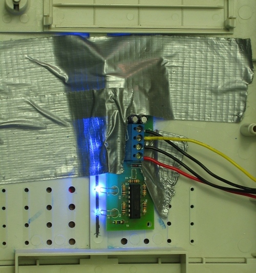
Cover the bottom side of the circuit board with a piece of black electrical tape, so that it will not short out your computer if the board touches a piece of metal in your case. Now it’s time to test the unit.
All hooked up and running properly
Turn the computer on carefully and be prepared to turn it off immediately if you smell smoke or anything seems amiss. If all goes well, the unit should light up as soon as the computer boots and starts accessing the hard drive. This is where I ran into a small snag; only the center light would light up. Hmmm… I pulled out my trusty multimeter and discovered that the power leads were only supplying 5.6 volts, instead of the proper 12 volts. Luckily, the problem was easily fixed. It turns out that I had connected the unit to a “fan bus” connector after all. As soon as the correct power leads were attached, everything worked flawlessly.
Step 4: Adjust the trimmer (optional)
The trimmer is a small black dial on the mod’s circuit board, which is turned to different positions using a small screwdriver. The trimmer controls “how fast” the LEDs react to hard disk activity. Run a few tasks on the computer (like starting a game) and watch the LEDs flash. Turn the dial to the lowest setting, the highest position, and then somewhere in the middle, while watching the LEDs. Stop adjusting when the lights flash just the way you like. Later, you can tweak this setting (if you decide you want the LEDs to react faster or slower).
Step 5: Mounting the unit in your case
Most people will choose to install this mod into an empty drive bay. It is much easier to remove a drive faceplate and drill holes in it, compared to drilling other holes in your computer case. First, clamp the unit to your work surface; I used a scrap of plywood to protect my table. If you don’t have clamps, hold (or tape) the faceplate firmly while drilling. If the faceplate has ridges on the back you should smooth them down using a Dremel tool, file, or knife. Then tape the template to the faceplate, so that it cannot slip and mess up your spacing. For best results, first drill small holes in the center of the template spots and then use progressively larger bits until you reach the final 3 mm diameter bit. Since I do not have the recommended 3 mm drill bit, I used a 1/8 inch bit for the final LED holes. If you don’t have a power drill, you can use a hand drill, a Dremel tool, or an X-Acto knife to make the holes, but please be careful: You don’t want to cut yourself .
Once youve made the holes, you should smooth the edges using a needle file or a narrow cone-shaped piece of sandpaper. Or you could use LED holders, as suggested in the installation instructions included with the kit.
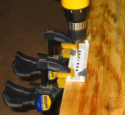
Drilling a drive faceplate using the template that comes with the kit
After the holes for the LEDs have been drilled, it is time to affix the circuit board to your system. You can use quick setting epoxy or epoxy putty for a permanent solution, use hot-melt glue, Velcro, double-sided foam tape, bolts (through the mounting holes in the circuit board), or even duct tape. Basically, you just want to keep the board from moving around, when your system is moved. If the board slips loose, it might short out your computer!
The 7 LED unit is clearly designed to be installed in an unused drive bay cover, but Ive got something unique planned for my mod, since I have one of the ugliest cases in existence. (Some people would do just about anything to improve the looks of this case.) My system has one particular issue that has annoyed me ever since I bought it (in addition to being ugly), which is that the power and hard drive activity lights are dim and hard to see. Also, my case had some visible damage from a previous modding attempt to increase airflow into the case, so I have chosen to install this mod to the front of my computer case and not in a drive faceplate.
Notice the masterful installation technique
While I was drilling holes in the front of my case for this mod, I also artfully widened the ventilation holes while I had the power drill handy. I’m quite pleased with the look of the progressively larger air-vent holes.
Step 6: Installing a diffuser
One of the goals of this mod was to hide a minor cosmetic issue with my computer case. In a previous mod attempt (to improve airflow into the case), I had used a Dremel tool to cut side slots in the center groove of the front of the computer. It was not nearly as hidden as Id intended, and I wanted to hide the flaw, not make it more visible with brilliant blue, flashing LEDs! Thats when I got the idea to insert a short piece of aquarium air tubing in the slot.
I first softened the tube by soaking it in hot water and then dried it thoroughly. I then used a pair of needlenose pliers to gently squeeze the tube into the center grove of my case. It stays put on its own, but Ill probably use a little superglue to make sure it doesnt fall off the next time I move my computer. The effect was nice, but not quite what I was looking for, so I cut some thin plastic strips from an old GPU cooler package and slid the strips into the tubing. I used a paper cutter to get the strips nice and straight, but Im sure you could use scissors. You could probably use fishing line as a suitable alternative to the plastic strips. I packed the strips in very tightly so they cant slide out, but will also superglue these in place, eventually.
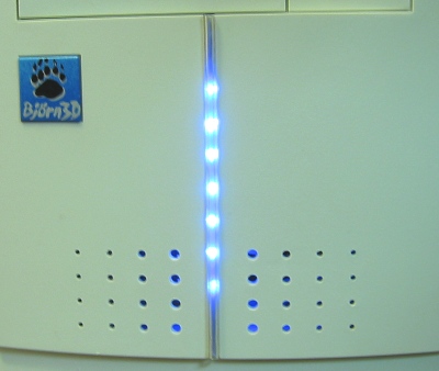
Im really pleased with the diffuser effect; the LEDs are highly visible from any angle
Advanced modding
Its possible to gang two (or more) of these units together, if youre looking for an impressive mod and you have a little more cash to spend. Basically, you just chain one unit to the next, as shown in the diagram below:
Wiring two units together
Here are a few ideas to get you started:
If you replace the LEDs, you will likely need to replace the resistors too, so heres a link to an LED resistor calculator.
Performance
The blue LEDs are small, but very bright. The bar-graph effect is very cool and it really works much better than a standard hard drive LED; during heavy disk access the whole thing lights up. It’s a dramatic effect. This device is quite visible and is easy to see out of the corner of your eye. You can even adjust the response sensitivity of the circuit, so that it has just the right amount of flicker for your tastes.
It’s a useful tool to determine your system’s status during gameplay. For example, Unreal II has a tendency to get bogged down on my system. When it does, I’ve noticed that the LED bar is completely lit, which (I think) means that I need more RAM (even though I have 512 MB).
Conclusion
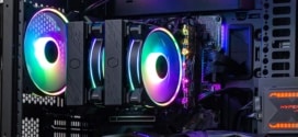
I’ve had the 7 LED unit hooked up to my system for a couple of weeks now, and I really love it! It’s a lot more interesting than my old hard drive indicator. It’s not only very cool, but it just plain works better than the single LED most cases have. Here’s the finished mod (click on the picture for a larger view):

This is a perfect ”beginner’s mod”. Basically, you need to be able to operate a drill and follow simple instructions to connect the wiring and mount it in your case. Use of a soldering iron is an optional step that may improve your connections.
For advanced modders, there are plenty of possibilities using multiple units. Or perhaps, you could upgrade the LED colors to match your case’s color scheme.
Here’s a short video (1.03 MB) of the unit in action:
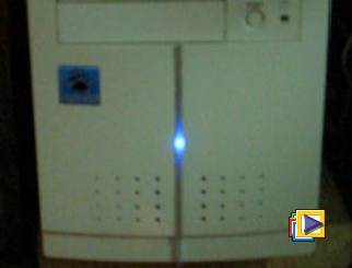
(Click image above to play video.)
The video shows Unreal II starting up, under 3 different lighting levels. Notice how visible this unit is! The reaction speed is set fairly low in the video, but you can easily speed it up ( if you prefer a display that flickers and draws more attention to your computer ).
Pros:
Cons:

Please feel free to drop by our forums to discuss this mod!