GigaByte has come back with a rock solid performing motherboard. Lets go see how the EX58-UD4P motherboard handled.
Since the introduction of the x58 chipset and the Core i7 CPU, it is kinda hard to determine which board is the better one or provides the most features. That includes the one thing we all like to have on our computers, which is, stability. And that’s whether it’s at default CPU speeds or when we overclock our computers just a little bit to gain that extra performance or overclock our components a lot. We all want to have stability. It does help to make overclocking a little easier and make the adjustments a bit more understandable as well.
With this being said, let’s take look at a motherboard from GigaByte, The EX59-UD4P. GigaByte is pulling out all of the stops on this motherboard, from the use of all solid capacitors and ferrite core chokes to a few more added features on this motherboard, that so far, (from what I’ve seen) other motherboard manufacturers have not used. Let’s get this show on the road as I run this motherboard through its paces and try to run it ragged.
About GigaByte
Founded in 1986, GIGABYTE started as a research and development team and has since taken the lead in the world’s motherboard and graphics accelerator markets. To truly reach out to all consumers, GIGABYTE further expanded its product portfolio to include more diverse digital products such as Notebook
and desktop PCs, digital home appliances, networking servers, communications, mobile and handheld devices, servicing every facet of people’s lives at home or at work.
Everyday, GIGABYTE aims to “Upgrade Your Life” by knitting a global network to effectively honor its commitment to world wide customers. What’s more important, GIGABYTE wishes all users to see and feel the brand through its products and all the touch points from GIGABYTE to the hands of all users.

SPECIFICATIONS
| Specifications |
| CPU |
|
| QPI |
|
| Chipset |
|
| Memory |
(Go to Memory Support List for the latest memory support list.) |
| Audio |
|
| LAN |
|
| Expansion Slots |
|
| Storage Interface | South Bridge:
GIGABYTE SATA2 chip:
iTE IT8720 chip:
|
| IEEE 1394 |
|
| USB |
|
| Internal I/O Connectors |
|
| Back Panel Connectors |
|
| I/O Controller |
|
| H/W Monitoring |
|
| BIOS |
|
| Unique Features |
|
| Bundle Software |
|
| Operating System |
|
| Form Factor |
|
| Remark |
|
| Note | (Note 1) Due to Windows Vista/XP 32-bit operating system limitation, when more than 4 GB of physical memory is installed, the actual memory size displayed will be less than 4 GB. (Note 2) For Windows Vista/XP 32-bit operating system only. (Note 3) For optimum performance, if only one PCI Express graphics card is to be installed, be sure to install it in the PCIEX16_1 slot; if you are installing two PCI Express graphics cards, it is recommended that you install them in the PCIEX16_1 and PCIEX16_2 slots. (Note 4) The PCIEX8_1 slot shares bandwidth with the PCIEX16_2 slot. When PCIEX8_1 is populated with a PCI Express graphics card, the PCIEX16_2 slot will operate at up to x8 mode. (Note 5) Whether the CPU/system fan speed control function is supported will depend on the CPU/system cooler you install. (Note 6) Available functions in EasyTune may differ by motherboard model. |
CPU Support List
| CPU Support List |
| Fx = Since BIOS Version OK = Test OK! N/A = Not support “-“ = Under Testing |
| Motherboard | Model | GA-EX58-UD4P(rev. 1.0) | |||||||
| PCB | 1.0 | ||||||||
| Vender | Model | Frequency | L3 Cache | Core Name | Process | Stepping | Wattage | QPI | 6.4GT/s |
| Intel | Core™ i7-965 | 3.2GHz | 8 MB | Bloomfield | 45nm | C0 | 135W | 6.4GT/s | F3 |
| Intel | Core™ i7-940 | 2.93GHz | 8 MB | Bloomfield | 45nm | C0 | 135W | 4.8GT/s | F3 |
| Intel | Core™ i7-920 | 2.66GHz | 8 MB | Bloomfield | 45nm | C0 | 130W | 4.8GT/s | F3 |
PACKAGING
|
|
|
|
|
|


Looking at the box that GigaByte used, we can see that this company added that little extra touch to make the packaging stand out. Also, GigaByte made sure you knew what this motherboard’s special features and unique capabilites were.

Upon opening the box we are greeted with another box that has the motherboard and also all of the cables and such we will need to use for this motherboard in our computer build.

As soon as we open the top part of the inner box we are greeted with SATA cables, IDE/Floppy ribbons (for those still using these devices), two SLI bridges (one for tri SLI, one for 2 way SLI), Rear IO plate, and another strange looking bag of contents. I will cover this a bit more later.

Removing the top items, GigaByte used a insert to protect the motherboard itself from the extras.

Removing the insert we finally see the EX58-UD4P motherboard wrapped in a anti-static bag.

Contents of the box are laid out here. In the top center is the motherboard and to the left are the IDE and SATA cables. Moving downwards is what appears to be a E-SATA port. Moving to the right from this bag are the two SLI ribbons, Rear IO plate, and the instruction manuals. GigaByte also included an SLI ribbon holder in with this motherboard, which is located right below the multilingual instruction booklet.

Now it is time to take a look at the E-SATA port. Looking at this power cable we notice it has both a Molex and a SATA power on it. This is the only time we have seen this design is on those adapters. It converts a Molex to SATA for power our internal HDD’s.

Up close view of this power cable.

GigaByte also used an odd looking SATA cable for this as well. It has both a SATA connector and a E-SATA connector.

Well, let’s look at the E-SATA connector. Hmm, Now it starting to make sense. We can use normal SATA HDD’s as external HDD’s without the need of purchasing a external enclosure for that HDD. Very ingenious design. Well, considering a SATA HDD and E-SATA HDD are basically the same thing, just the connector is different.

In order to use this adapter, we need to use two of the SATA ports on the motherboard and hook up the Molex power to our PSU.

What you will get with the E-SATA/SATA connector.
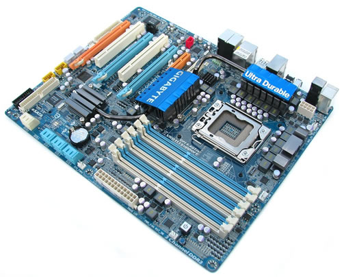
OVERVIEW
It’s time to give a good look over on the GigaByte EX58-UD4P motherboard.
 |
Starting off on the rear IO ports of the motherboard here. For the amount of ports on the back of the motherboard, it’s not overly crowded. GigaByte still uses the ever aging PS2 ports. Moving to the right, the digital audio ports are found here. We have one FireWire port, and since almost all the newer motherboards are using a rear clear CMOS button nowadays, it’s a welcome sight to see it included here as well. Moving to our right, we have a stack of four USB ports, then a stack of two USB ports, and two more USB ports are topped off with a GigaBit LAN port. Then, finally the 7.1 audio rear ports. (as always, GigaByte uses Realtek’s HD audio like so many other manufacturers do). What we don’t see is dual gigabit LAN capabilities on this motherboard that many other manufacturers use on their motherboards.
 |
Now it’s time to go over the lay of the land. GigaByte used eight SATA 3GBs 180° ports for this motherboard. This will definitely help out for those with extremely long video cards that normally block access to these ports. You need to know that the Southbridge only officially supports six SATA ports natively, the other two are on another SATA controller (G-SATA), so for you raid users, put your OS on one of the six light blue SATA ports first and work from there.
 |
Looking at the SATA ports from a top view. Starting from the upper left hand corner, the EX58-UD4P motherboard has an extra four USB headers for use on the front USB headers. Staying close to the edge of the motherboard and moving downwards, the front IO (power/reset, lights) ports are found here. To the right of the front IO ports is an IDE ribbon. This connector is also controlled by the G-SATA controller located right behind the IDE port. Still moving o our right we have the Southbridge, ICH10R, with a rather unique heat sink. To the bottom right hand corner of the Southbridge we have the CMOS battery. Then, on the far right hand side of the SATA ports is fan header #1.
 |
Moving to the right, we find ourselves over the memory ports of the EX58-UD4P motherboard. The numbering of the memory ports is a tad odd in the way they are numbered and have to be used. The white memory ports are 1, 3, 5 and the blue ones 2, 4, 6. With three or less memory sticks you need to use the white ones first, starting from the upper one (closest to the CPU). Immediately below the memory ports we see two sets of surface mount LED’s and also the main 24-pin power plug. To the upper right hand corner above the memory ports is another set of LED’s. Well, actually, they’re everywhere and also have a specific purpose. The ones shown here are the ones that are easier to locate. I will explain these LED’s in a bit. On the bottom right hand corner is the on-board power button and the little blue looking dot switch that is below the onboard power is the reset button. Right below the reset button we see fan header #2.
 |
Moving upwards towards to CPU socket. We can see the CPU socket (well, of course if we moving towards it, LOL). To the far right on the edge of the motherboard we have six analog CPU phase power chokes with a pretty cool looking heat sink over the power mosfets. Right above these phase power mosfets is the EPS CPU power plug. This plug is orientated backwards and is also in a difficult spot, so if you have a large chassis it is a good idea to make sure you have an EPS power plug extension. To the left of the EPS CPU power plug is another set of analog phase power chokes, again with a really nice looking heatsink over the power modules themselves. I should have mentioned this earlier. This motherboard uses a heat pipe that starts at the Southbridge, goes to the IOH (Northbridge), and finally ends at the upper most power mosfet cooler. To the left of the CPU socket is the IOH (Northbridge), again really nice looking heat sink, right above the IOH, we see two more chokes and a rather little heatsink right above these. GigaByte made sure the two phase power for the IOH stays cool as well to helps with stability. Despite all of these items on or around the CPU area, there is enough room to use large heat sinks, short ones, or water cooling. I forgot to mention the fan header nearest the EPS CPU power plug. This makes fan header #3, and fan header #4 is located to the right upper memory port.
 |
Just a better shot of the IOH heatsink.
 |
The EX58-UD4P motherboard has three PCI-E x 16 ports (two blues and one orange), two PCI ports, one x4 PCI-E port (nearest to CPU) and one x1 PCI-E port. Also, while looking at the two upper PCI-E ports, you can see that they are really close to the IOH heatsink, basically rendering any large PCI-E x1 cards useless on the PCI-E x1 port. And from the looks of it ,the x4 PCI-E port comes really close to the IOH as well. I will investigate the PCI-E port in a bit. Looking in between PCI-E x1 and the x4 ports, there is fan header #5. The EX58-UD4P motherboard uses a dual BIOS. This is for those who brick their perfectly good motherboard when trying to flash this motherboard. If a flash fails, the EX58-UD4P supposed to reflash it back to the last best known BIOS (nope, I did not feel like testing that portion out, so your burned). These are located in the upper left hand corner of the motherboard right above the FDC port. Yes, I said a floppy connector port. OMG, make the bad floppy go away. Right below the FDC port is fan header #6. Man, these fan headers are everywhere.
 |
A better look at the FDC port and the Dual BIOS chips on this motherboard.
 |
Closer look at the IDE port and the four extra USB ports also the G-SATA controller.
 |
A better view of the EPS CPU power plug. Kinda tight in that area.
 |
The PCI-E x4 port has a missing back stop to it. Above this port is the primary PCI-E x16 video card port, the second PCI-E x16 video card port, and the last video card port is a x8 PCI-E port (denoted by the amount of pins in the port). Now, this mother board is capable of handling two SLI cards or two Crossfire cards in full x16 bandwidth. When using three or more video cards in SLI/Crossfire, your bandwidth is shared between PCI-E port 2 and 3 and is reduced to x8 on both of them (i.e. x16, x8, x8 for Tri cards, or x16, x16 for dual video cards). I should mention there are three more 1394 on-board ports. The PCI-E ports are only spaced apart by one PCI port. So, if you have two or more video cards and a PCI device, you have to make a choice of either ditching the PCI device or the video cards.
 |
Yes, the PCI-E x4 does clear the IOH heatsink, but just barely. But that bottom screw may be an issue.
 |
The PCI-E x1 port is useless to use large cards on this port.
 |
See the bolt I am talking about on the IOH heatsink? It lines right up with the PCI-E x4 port.
 |
Time for those LED’s. I am going to start off with the ones right above the main 24-pin power plug. These are for diagnostic reasons for various roles around the motherboard, CPU, memory, IOH, QPI, PCI-E ports, etc. etc. If you go a tad too far on voltage on a specific part of the motherboard, these will light up yellow, red, orange, or green. These paticular ones light up red, orange, green during posting and as soon as the OS loads up, they will turn off. If they stay lit, you got a problem.
 |
The next set of LED’s. The first set of five LED’s are blue and they stay blue the entire time. The set below these (the long string of them) do the exact same thing as the first set. They light up green, red, orange, during posting and will turn off as soon as the OS loads up. If they turn yellow or stay lit during the OS, you need to find the cause of this.
 |
It’s the same story with these as the last two sets of LED’s. GigaByte made sure to give you a visual warning if you have gone too far on voltage or if there’s going to be a potential problem with this board (to prevent serious damage).
 |
Finally, the entire motherboard. Not too bad of a layout. Could have been a tad bit better, but should not cause to many major issues.
 |
||
 |
 |
 |
 |
 |
 |
 |
 |
 |
These are here for your viewing pleasure. So, please take a minute or two and look over the heatsinks and such.
INSTALLATION
As always, I need to install this motherboard in order to test it and attempt to give it a smokey flavor.
 |
 |
Me, installing the CPU retention plate onto the EX58-UD4P. I always use a retention plate on all of my computers.
 |
What the backside of the motherboard looks like. GigaByte used retention style brackets to help keep the motherboard from getting warped when using the heatisnks on the IOH heatsink and on the Southbridge heatsink.
 |
What it looks like after all four bolts are fully secured to the CPU socket mounting holes.
 |
Just an up close image of how I secured the bolts to the motherboard. I put a neoprene washer in between the nut and motherboard to prevent damage.
 |
First, we need to unlock the little swing over lever, then open the holding mechanism so we can place our CPU in the socket.
 |
Remove the CPU ZIF cover.
 |
What the 1366 socket looks like naked.
 |
Insert the CPU.
 |
Then lock down the CPU holder over the CPU, making sure the swing out lever is over the holder.
 |
Like so.
 |
Put the rear IO plate cover onto my chassis.
 |
Motherboard installed and tightened up.
 |
Hooked up the four SATA cables for my three HDD’s and one DVD burner.
 |
Next comes the CPU. Yes, the water is being pumped through both the CPU block and the video card blocks. DO NOT try that at home. I specifically engineered my water cooling to do just this type of tasking. I even have a risk of water spraying everywhere.
 |
CPU block fully installed.
 |
Video cards installed and hooked up.
 |
Making one last look over before I continue on.
 |
System up and running, This is a night time shot of what the GigaByte EX58-UD4P looks like.
BIOS PART I
I am not going to get into a lot of detail over the BIOS itself as there are a lot of pictures. These are here for you to get familiar with the BIOS. The Next BIOS page is all about overclocking.
|
|
|
|
|
|
|
|
|
|
|
|


As we can see, the GigaByte EX58-UD4P motherboard’s BIOS is very well laid out. Also, it has that familiar look to it we have all come to know, so navigating through the BIOS to make adjustments should be real easy.
BIOS PART II
This portion of the BIOS is all bout the settings we can make to our CPU’s, memory, voltages, and tweaks to other various parts of this motherboard. It’s better known as the M.I.T.


When you enter this BIOS portion you will be greeted with several different general adjustments. On this screen, I did have small inconvenience when dealing with the XMP profiles of the memory when I tuned on that setting. If I adjusted the CPU multiplier downwards, and also adjusted the FSB up, and then turned on XMP after making those adjustments, it would default the CPU multiplier and the FSB, forcing me to readjust them once again.

Lets start from the top of M.I.T. sub menu and enter the advanced CPU features to look at the advanced CPU adjustments we can make.

As we can see in this sub-menu of the M.I.T. BIOS, we can have complete control over the CPU. I can turn off Hyper-Threading, Disable/Enable CPU cores and also turn on or off the power saving adjustments of the CPU itself.

Hitting ESC button on the keyboard bring us back to the main menu. Let’s enter the QPI/Uncore sub-menu. This is where you can adjust the QPI’s divider and the Uncore multiplier (it made no difference on my Core i7 920 CPU if I adjusted these). Isochornous Support is here and I have no clue what this setting does, so I left it default (Enabled).

While we are back into the main M.I.T. BIOS page let’s locate and enter the Advanced Dram Settings page. In this portion of the BIOS we can make our memory adjustments for timings, voltages, and even the divider (Auto, 6, 8 are the only ones available). If you are using an XMP memory type you can set that profile as well. You will notice this portion lists all memory ports used individually, which is broken up into two sub-menu’s per memory stick. This BIOS has a lot of settings and can overwhelm anyone not familiar with this type of BIOS.
|
|
|
|
|
|
|
|
|


Each channels memory settings are shown here. On the left side are the primary timings. And to the right side is the Turn Around Settings page for each memory stick used on this motherboard.

After making our settings in the Advanced DRAM Settings page, it is time for us to return to the main page of the M.I.T. BIOS page and go to our final page of Advanced Voltages Settings. As we enter this page we are again overwhelmed by the amount of voltage settings we can make. So tread lightly.
The M.I.T. Bios page has a lot of information and adjustments for the EX58-UD4P motherboard. Almost to the point it can overwhelm the novice. What makes making these settings a lot less overwhelming is that GigaByte made sure you knew exactly what the default setting were per adjustment.
I want to mention this BIOS did not have a place where we could save our BIOS setting through profiles, which makes overclocking this motherboard with multiple settings, or overclocks, an absolute pain. If you do have to reset the BIOS for any reason, you will have to reset every one of these settings back to where you were last stable at. That makes it double as hard because of complex multiple settings that are already present. I ended up writing down everyone of my settings on a piece of paper prior to making any tweaks to the BIOS.
TESTING METHODOLOGY
| Test Setup &Testing Methodology | |
| CPU | Lapped Core i7 920 |
| Motherboard | MSI X58 Platinum, GigaByte EX58-UD4P |
| Case | Coolermaster ATCS 840 |
| Memory | Corsair DDR3 1600 |
| Video Card’s | Sapphire 4870×2, HIS 4870 |
| Hard Drives | 3 x 160 Gig Sata2 Western Digital, 2 in raid 0, 1 back up |
| CDRom Drive | Lite On Sata1 DVD Burner |
| Power Supply | Coolermaster U.C.P. 900watt 80+ Silver |
| Type Of Coolers Used | DD MC-TDX , Koolance VID-487X2 (Dual Loop), VID-487 Koolance |
| CPU Speeds Used | 3990Mhz, 210 x 19 |
| Operating System Used | Microsoft Windows Vista 64 bit Ultimate |
| Type of Software Used During Testing | Far Cry 2, Everest, Sisoft, Crystal Disk, ATTO, wPrime, Super PI, Win RAR, CineBench, POV Ray, Crysis, 3Dmark06, 3DMark Vantage |
I ran each of the above listed programs three times, each time looking for consistency and stability. The only CPU clock speeds I used were 2.66GHz (default CPU) and my ever stable max overclock of 3.990GHz. The motherboard I will be using as a comparison is the MSI X58 Platinum (non SLI). The MSI motherboard will only be listed as stock default CPU speed of 2.66GHz. For game testing I used an ATI “Tri Fire” (one 4870 and one 4870×2 in Crossfire mode). Also, these video cards were not overclocked and were left at their default clock speeds. A resolution of 1680×1050 was used as well as maxed obtainable settings per game. The 3DMark benchmarking was used with the default settings of 1280×1024.
For POV Ray testing I felt that rendering the multliple frames of the animations would better demonstrate each motherboard’s capabilities. The three animations I chose for this task were Camera, Ambient, & Glsbng. The resolution I used was 1024×1024 (AA 0,3).
Crysis Benchmarking was conducted with both default CPU and GPU benchmarking with HOC benchmarking tool.
I did not list the overall scoring of each of the 3DMark benchmarking programs. I instead listed the individual scoring.
WinRar Testing was done only with multi threaded benchmarking. I let the benchmarking tool count up to 500 MB/s compression and recorded the time it took to reach that and the result.
For the HDD testing, I used only my Western Digital 160 RAID 0 array (320 GIG total).
OVERCLOCKING
The one thing the EX50-UD4P motherboard was smoothly was Overclocking. I never had such an easy time of getting my CPU to a core speed of 3990MHz, 210×19. I quickly found out once again (on three separate motherboards) that this CPU is incapable of going beyond 3990MHz and over an FSB of 210. No matter what I tried, this CPU was not going to budge. Even though I left the V-Droop setting off, this motherboard still provided a good stable voltage to my CPU, IOH, and PCI-E x16 video card slots. I was unable to move the PCI-E frequency above the default setting of 100 MHz. It’s a shame really that GigaByte did not make that adjustment separate from the rest of the motherboard’s frequencies (better known as PCI locking). To add to my Overclocking endeavors, this motherboard posted with the default CPU speed of 2.66GHz with relative ease and no major adjustments were needed to get this motherboard to post. The XMP profiling actually works and will set the memory speed accordingly. However, like so many other X58 motherboards, it kept setting the command rate to a 1T, while most memory uses 2T. Also, on the XMP profiling (once I started to move the FSB upwards), this board would keep the memory divider it was using while in a default CPU speed (i.e. 1600=nx133 and n= 12 memory divider). So, no matter that I was at 133 FSB or 200 FSB, as long as I kept the memory divider at auto and had the XMP profiling turned on, the memory divider would stay at 12. Until they come out with memory doing 2400 MHz, I had to use an 8 memory divider.
Let’s start off with the Southbridge and its subsystem testing.
ATTO
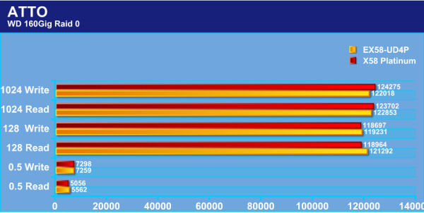
Higher=Better
It’s a hard decision to claim which motherboard has the lead here. During the 0.5 Read the EX58-UD4P beats the X58 Platinum. But the X58 Platinum teaks the lead in the writing portion of the 0.5 testing. The EX58-UD4P Takes the win in both Read and Write during the 128 testing. Then, it changes hands and the X58 Platinum takes the win during the 1024 testing. If these two motherboards were boxers, they both be bruised.
Crystal Disk
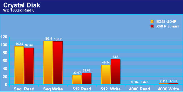
Higher=Better
With Crystal Disk benchmarking, the only time the EX58-UD4P motherboard took the lead was during the Sequential testing. The X58 Platinum outperformed in both the 512 read/write and the 4000 read/write testing. Now, keep in mind, this is being tested on a set of drives where my OS is installed and these scores varied greatly from test to test.
SiSoft
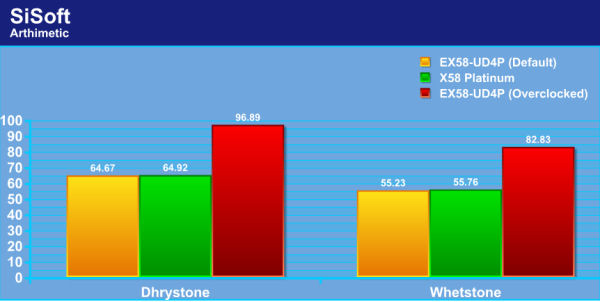
Higher=Better
The performance is so close to one another it’s impossible to determine who is the clear winner. Both of these boards performed on par with each other.
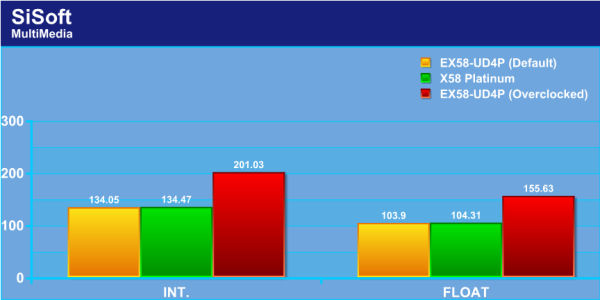
Higher=Better
In MultiMedia we see the same closeness as the Arithimetic testing.
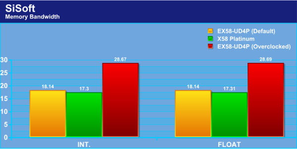
Higher=Better
Let’s see how these two motherboards stack up to each other during Memory bandwidth testing. This should prove to be interesting. Well, I wasn’t disappointed with the GigaByte’s memory performance. Having a good XMP profiling ability really showed the benefits.
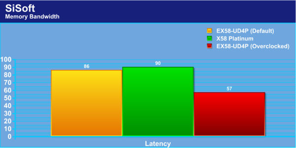
Lower=Better
The motherboard with the highest memory clock also gets the best latency.
EVEREST
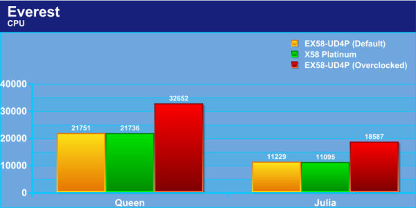
Higher=Better
Boy, these two motherboards are swinging at each other and cannot seem to connect a punch to one another. As we are seeing with SiSoft benching, both the X58 Platinum and the EX59-UD4P motherboards are about evenly matched.
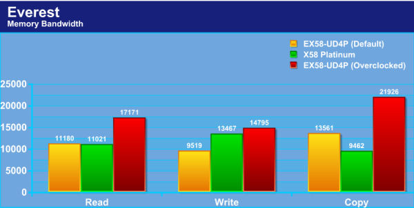
Higher=Better
Oh wow, now we see some excitement. During the read portion of memory testing, the EX58-UD4P takes a slight lead. During write testing the X58 Platinum takes a commanding lead. The EX58-UD4P takes the win with the copy portion testing.
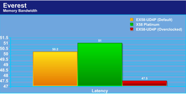
Lower=Better
Well, since the EX58-UD4P motherboard has a better memory clock during default CPU speeds, it naturally has the lowest Latency.
wPrime
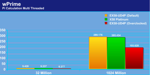
Lower=Better
With wPrime testing the X58 Platinum motherboard performed slightly better than the EX58-UD4P.
Super Pi
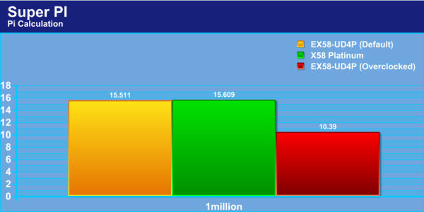
Lower=Better
When calculating with Super PI, the EX58-UD4P motherboard was the clear winner.
WinRar
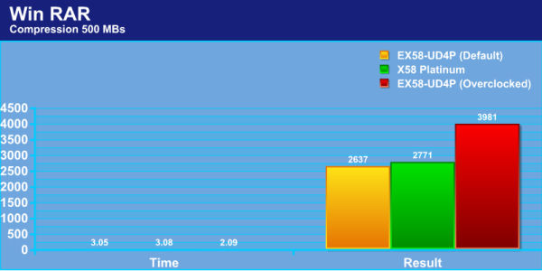
Time: Lower=Better, Result: Higher=Better
Now with WinRar testing, it is a little confusing. Normally, by having a higher result, the time it took to compress a 500MB/s file is lower. Not in this case. The EX58-UD4P motherboard took the win in total time, but the X58 Platinum had the win on the actual result.
CINEBENCH
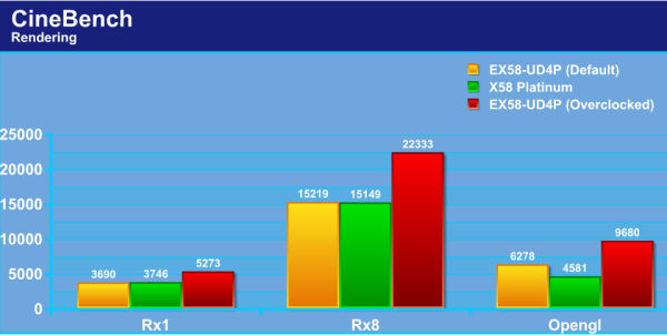
Higher=Better
While rendering with 1 CPU core (Rx1) The X58 Platinum motherboard held the lead here. During the multithreaded portion of testing (Rx8), the EX58-UD4P motherboard has the slight advantage. During the opengl testing, the X58 Platinum did not stand a chance against the EX58-UD4P.
POV RAY
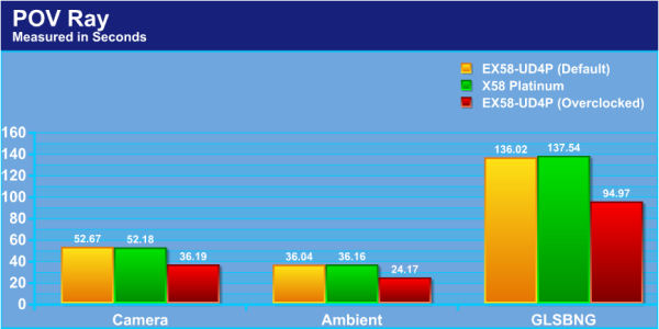
Lower=Better
When rendering all three animations in POV Ray, it is too close too call the winner.
3DMark06
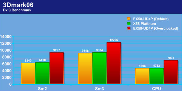
Higher=Better
No clear winner with 3DMark06 benchmarking as both motherboards are about evenly matched.
3DMark Vantage
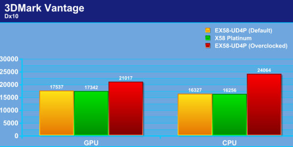
Higher=Better
As we saw with 3DMark06, it is too close to call a clear winner.
CRYSIS
CPU
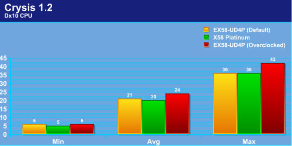
Higher=Better
As we all know, Crysis still gives a good work out with our machines. Only being one frame rate higher (EX58-UD4P), IMO, is not enough to claim the win.
GPU
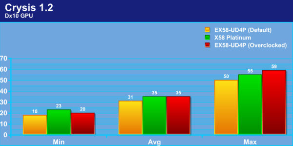
Higher=Better
The X58 Platinum motherboard has the better overall win here.
FARCRY2
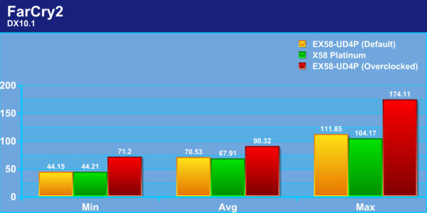
Higher=Better
The EX58-UD4P motherboard starts to show its might during FarCry2 testing, taking the lead in both average and maximum frame rates.
CONCLUSIONS
Like many other X58 motherboards, the GigaByte EX58-UD4P performs quiet well. But it’s not just the kind of performance that separates one company from any other. It is the features that each has that separates them. In this category, GigaByte has a definite lead. By utilizing two 2oz copper plates in the PCB, a copper heat pipe design, three PCI-E X16 ports capable of handling Tri Fire or SLI with the greatest of ease, this motherboard is the most stable motherboard I, myself, have used. Going from a FSB of 133 to 210 FSB was, simply, an easy task to do. Also, this is one of the first motherboards I have seen that has a working XMP profiler. Normally, I just turn this feature off because it causes more headaches than what it is worth, especially when cranking the FSB.
The overall layout of this motherboard is good, not great, but good. Everything was easily accessible and clearly marked, but there could have been some improvements. The one thing that sticks in my head are the PCI-E x1/4 ports. They’re close proximity to the IOH (Northbridge for you laymen) will make using these ports extremely hard. Not having one PCI port available will also make those who use this older port (like my self with my Audigy sound card) null and void if you are also using two or more video cards (like my self again). GigaByte should have moved the IOH up a bit more and placed the PCI port right above the first PCI-E x16 port and then used a x4 PCI-E port as the upper most port. This would allow some of us the use either the PCI or PCI-E port. The one thing that I feel that really hurt this motherboard the most was not being able to have a BIOS profiles (saving multiple BIOS settings). During my overclocking and tweaking, I found myself having to reset the BIOS a couple of times. In turn, I had to remember all of my settings that I used that were my last known stable settings. The placement of the EPS power plug is in an awkward spot and will make getting to this plug a real challenge in tight cases (90% of the cases out there will have issues).
During my testing of this motherboard, the IOH nor the motherboard got excessively hot. By placing a fan on the cooper heatpipes upper point (the power modules), I was able to keep my temperatures under control. Looking around the web for a pricing of this motherboard I seen it goes for around $270 USD which is a tad high, especially with other comparable offerings for cheaper.
- Performance 9
- Value 7
- Quality 9
- Warranty 9
- Features 9.5
- Innovation 9
Pros:
+Ease to understand where goes where
+Diagnostic LED’s
+Stable performance
+Cool running
+Tri Fire and Tri SLI capable
Cons:
–No BIOS profile saving
–PCI-E x1/4 too close to the IOH
–The EPS power plug in awkward spot
Because of the stability I had with this board I feel it was best to give it a, Final score of 8.5 out of 10 and receives the Bjorn3D Seal of Approval.