We have some early preview shots of the Gigabyte GA-EP55-UD6 which is slated to be the top of the line Lynnfield Gigabyte board for core i5 CPU’s.
INTRODUCTION
At Computex 2009 Gigabyte revealed their GA-EP55-UD6 flagship Lynnfield/Core i5 motherboard and we managed to get a behind closed doors look at the board. We have to tell you with the P55-UD6 and it’s 24 phase power and 2oz copper PCB design and a host of advanced features GiGabyte pulled out all the stops on this board.
While these boards weren’t ready for a full production run it’s nice to get a look at the planed design and drool over some of the advanced features that promise to take a Core i5 CPU and make it scream for mercy.

Since Core i5 boards are slated to use Dual Channel DDR3 we were suprised to see 6 ram banks on the P55-UD6 and having six means you could use up to 24 massive gigabytes of DDR3 dual channel on this beauty.
Before we get to far into the drool portion of this board lets move onto the Layout section where we can get a better look at the Flagship P55 Lynnfield board.
The Layout
Lets just jump into the layout pictures section without a lot of yada yada yada because the pictures will tell most of the story on this (Mostly) well laid out board.

Taking a top down view on the board the first thing we noticed is the first PCI-E 1X slot is going to be obstructed by the Northbridge heatsink and we haven’t seen any PCI-E 1X cards that would fit into that arrangement with the NB being so tall. Then the 8 pin CPU connector (Upper right corner) is in a spot that might cause a little aggrivation when connecting it. An Easy method around that is to install the PSU first, then connect the 8 pin CPU connector prior to mounting the board. Depending on the CPU cooler you choose it might not be wise to wait until after board is mounted to connect the 8 pin. Notice the onboard power on switch right below the ram banks, to the right of the two solid ferrite chokes. That’s a little bit of an odd spot but if your doing some pre-front panel header connection testing it’ll come in handy.

A whopping 10 Sata connectors with 6 being marked as Sata 2 and 4 being marked GSata we’ve learned that there was some problem with the Marvell controller on this board but we have no information on what will replace it. We would assume (and you know what assuming can do for a person) that a controller with the same layout will be used and we have high hopes it will be another Sata 6G capable of handling next generation 6gb/s drives. We haven’t seen any 6gbs drives out yet but if Gigabyte is putting the controller on the Flagship P55 Lynnfield board you can bet we’ll be seeing them soon enough.

Switching to the side we get a look at the majority of the boards connectors and you’ll have plenty on the P55-UD6, upper left the color coded front panel connector, a couple of USB headers, a firewire, legacy Pata IDE controller, fan header, and a Com port header. Notice the LED diagnostic readout in the lower right hand above the front panel connectors. That’s a nice feature if you happen to run into any trouble during setup. Barely visible between the front panel header and first USB header you can barely see the reset cmos button, and by the lower right hand corner of the Southbridge cooler behind the white GSata port a reset switch.

Taking a close up of the Southbridge cooler we find it reminiscent of a race cars stripe design. Notice if you end up using a dual slot cooler card the CMOS battery might be a little hard to access. With an onboard CMOS reset switch that shouldn’t be much of a problem.

Moving from the SB to the Northbridge heatsink we see an advanced heatsink design with a lot of surface area to help dissipate the heat from the heavy OCing this board is likely to see. We get this question a lot, so take a gander at the silk screened lettering below the NB. It says PCH Heatsin, so when you stumble into BIOS wondering what they call the NB think PCH and you’ll probably be on the money.

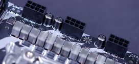
Getting into the CPU area we were set aback by the 24 Ferrite chokes to the top and left of the CPU. That means 24 phase power for rock solid power delivery to the CPU. When combined with the solid Japanese capacitors and the top end power delivery system this board is sure to be a force when overclocking the core i5 CPU’s.

The CPU has a new hold down scheme for the lever and once you raise the lever the CPU hold down moves back and clears the single bolt in the front and you can remove the Foxconn CPU socket protector. We would hazard a guess (not so much a guess) that this board was manufactured to Gigabyte specification by Foxconn. No need to pull your hair out there Foxconn produces a lot of major vendors boards and is the worlds largest motherboard manufacturer.

We already addressed the PCI-E 1X slot almost out of the picture to the right being almost useless because of the NB heatsink. Given that this is going to be the Flagship board of the Gigabyte P55 lineup we would expect most end users to have a dual slot cooler GPU installed so you will most likely lose the second PCI-E 1X connector because the dual slot cooler GPU will obstruct it. Then we see a normal PCI followed by another PCI-E 16X staggered with a second PCI followed by a third PCI-E 16X. If the P55 Lynnfield follows the same pattern as the P45 chipset did the first PCI-E 16X slot (Blue) will run at 16x and the two orange will run at 8x but that’s a guess at this point.
Layout Cont.

There’s a close up of the color coded front panel connector and the Diagnostic LED readout panel. The black switch is the Clear Cmos button and the Blue switch is the reset button.

The back I/O panel shows a copious selection of I/O options. EIght (plus 4 internal headers) external USB 2.0 ports, the usual 6 jack Audio ports, Toslink and Coaxial and Analog sound out, what looks to be two self powered E-Sata ports, a Dual purpose Keyboard/Mouse port, firewire 400 and 800 ports, and dual Gigabit lan ports. The simple abundance of ports on the P55-UD6 is going to make it one of the most flexible Lynnfield boards out there.

Getting back to the CPU area for a moment notice that the heat sinks around the CPU are also advanced design heatsinks, combined with the 2oz copper PCB and 24 phase power this board is looking good for some massive overclocking.

Backing up a little from the CPU area you get the impression it is indeed a race car stripe design on the heatsinks.

We still can’t get over the 6 ram banks that should hold up to 24gb of dual channel DDR3 and find ourselves wondering if this isn’t a design leftover from the X58 chipset since the P55 is likely more an offshoot of X58 than a new design.

Then we’ll leave the pictures section with a top down shot to increase the drool factor a little and move onto the features section which will be a little sparse until we get hands on our own P55-UD6..
Features
We mentioned that the features section would be a little sparse, when you get 15 minutes behind closed doors with a new board there’s no manual or website specifications to study so we can only go with what was on the whiteboards behind the product. We were lucky we managed to snatch the board down for closer inspection and avoided the whole whiteboard reflection problem.
We mentioned that the Gigabyte P55-UD6 has 24 phase power and 2oz Copper PCB. The 24 phase power is slated to be 24 Phase 6 Gear power adhering to the VRD 11.1 standard for power savings and seamless power delivery to heavy CPU load periods. The advantages of the 2oz Copper PCB design is lower impedance, lower impedance means more energy efficiency. The 2oz of Copper will also help to distribute the heat generated by the board more evenly than traditional 1oz Copper boards. It should also result in better memory overclocking and lower voltage needed to run the ram which contributes to a cooler system. As a byproduct of the heavy Copper design we get a lower Electro Magnetic Interference than traditional boards which is also boosted by good design layout of the circuits on the board. Another benefit is the 2oz copper ground layer of the P55-UD6 is it will withstand a bigger static electric shock (about 10% more) than traditional 1oz copper PCB boards.
We don’t have many details on it but we wanted to mention Smart 6 a combination of 6 innovative software utilities that allow you to spped up the system, reduce boot up time, manage a secure platform, and recover user settings with a mouse click. The listed utilities are.
- Smart Dual BIOS: Two Physical BIOS chips
- Smart QuickBoot: Speeds up system boot time
- Smart QuickBoost: Quick and effortless CPU OCing for the novice and experienced OCer
- Smart Recovery: Roll back to previous system settings to a known working status
- Smart Recorder: Monitors uptime and when the PC was turned on and off and even large file copies
- Smart TimeLock: Allows parents to schedule PC time for children
You’ll also get the benifit of Dynamic Energy Saver 2 a combination of software and proprietary hardware that can control the flow of power to the CPU, Memory, Chipset, VGA HD and system fans. Dynamic Energy saver 2 will also seamlessly give the system all the power it needs during heavy overclocking and heavy load periods maximizing power savings while giving you all the power you need for OCing and heavy load periods.
You’ll also enjoy a Smart Dual Lan with two physical Gigabit LAN chips offering hassle free zero downtime capibilities. If LAN chip one happens to fail the second LAN chip will automatically kick in and switch to the port your using with no downtime. You can also team the Gigabit LAN ports which effectively doubles the bandwidth of the LAN connection.
For security purposes you will have a TPM chip which is a Trusted Platform Module Chip and provides a 2048 bit encryption and can store a digital key on a USB thumb drive. Gigabyte Smart TPM allows you to lock the TPM by cellphone or Bluetooth a new feature we haven’t seen except on this board.
Then finally the P55-UD6 should incorporate the new 6Gb/s Sata interface if the specifications we saw hold true on the final design, last we heard there were a few bugs in the Marvel 6Gb/s controller initially slated for the P55-UD6 so it will be a waiting game on the final selection of the 6Gb/s controller. We are hoping that GIgabyte isn’t forced to back up and use the 3Gb/s interface due to production problems on the intended controller.
CONCLUSION
The Gigabyte P55-UD6 looks to be a killer board for energy savings and overclocking ability. It incorporates the best features Gigabyte can offer along with 24 phase power delivered by Ferrite chokes and solid Japanese capacitors but this being a preview we’ll have to have hands on before we commit to marriage to the GIgabyte P55-UD6.
If Gigabyte holds true to the UD6 series boards we’ve seen we’re sure the P55-UD6 will be a top of the line monster overclocker with more bells and whistles than the normal enthusiast will ever use.
We should have a P55-UD6 production model in our hands during the upcoming Core i5 launch and do a full review complete with spanking new Core i5 CPU so if your looking for a little more power than LGA 775, a little less expense than Core i7,and a killer board to put the new dream machine on we would suggest coming back to check out the full review on the Gigabyte P55-UD6 when we try and fry a fresh Intel Core i5 CPU until it screams like your little sister when you put a frog in her hair.