Unboxing the Gigabyte X99-UD4P Page 2
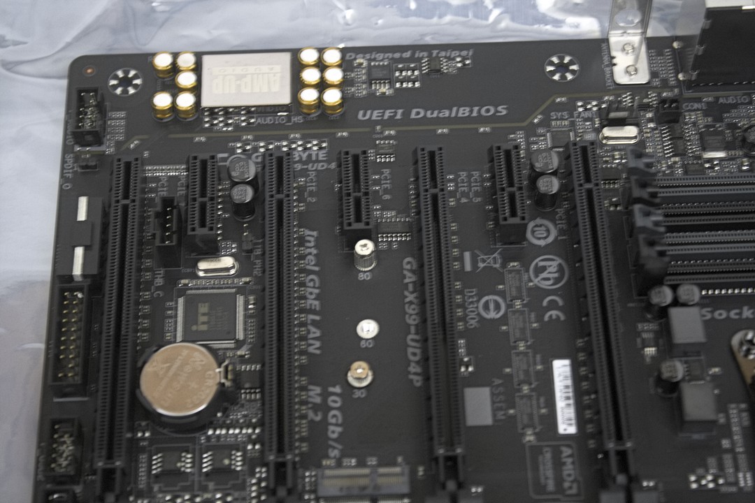
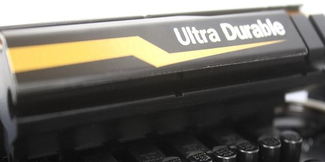
Turning our attention over to the PCI Express expansion area of the motherboard and moving from right to left, we get a full PCI-E x16 expansion port, a X1 PCI-E, X8 full-length PCI-E, X1 PCI-E, X16 PCI-E, X1 PCI-E, and finally we get another full-length PCI-E X8 expansion port. These will vary on the amount of PCI-E lanes available to you by the type of CPU you are going to be using. If you need any clarification, please go back to the Specifications section of this review, or you can look it up at Gigabytes Website HERE. In between PCI-E port 3 and 5 (the full length expansion ports from right to left) are two more small connectors used for a M.2 SATA Express card and a Wi-Fi card. Next to the last two PCI-E expansion ports is a Thunder Bolt Header (THB). This header will be used once you install a Gigabyte Thunderbolt expansion card (not included). Just below the THB header is a CMOS battery. Towards the edge of the motherboard, and lower left of the picture moving up, are two USB 2 expansion headers, up from the USB 2 headers is an TPM (Trusted Platform Header), and a standard 4-pin MOLEX power connector that needs to be plugged in if you plan on using multiple video cards. Just above the 4-pin MOLEX connector is a front audio header. Just above the PCI-E expansion ports is a small yellow line that seems to separate that portion of the motherboard. This area is designated just for the audio portion of the motherboard. This “border” exists to ensure that we get the best listening experience without interference from the rest of the motherboard.
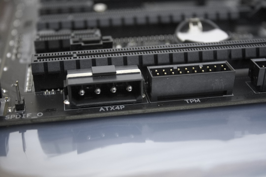
Here we have a closer image of the 4-pin MOLEX connector that will need to be plugged in when using more then one video card in either SLI or Crossfire configurations.

The two M.2 connectors that are nestled in between PCI-E expansion ports 3 and 5, the lowest or most reward M.2 connector is for an expandable Wi-Fi card (not included). This is so we do not have to use a PCI-E expansion port if we want Wi-Fi capabilities on this motherboard.
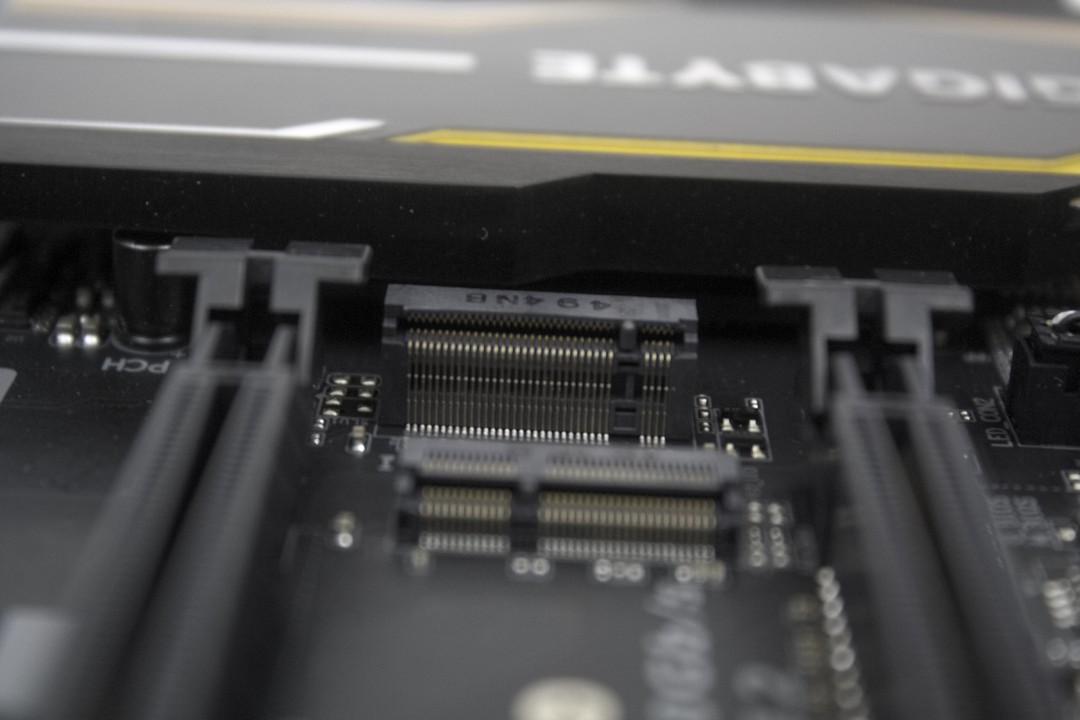
The most forward M.2 connector, (One closest to the PCH heatsink) is for SATA Express add-on cards. Now keep in mind, if you do plan on using a M.2 style SATA Express card, it will disable any SATA Express Storage devices hooked up to the SATA Express storage connectors located on the outer most edge of the X99-UD4P (The large, gray SATA 6Gb/s expansion ports).
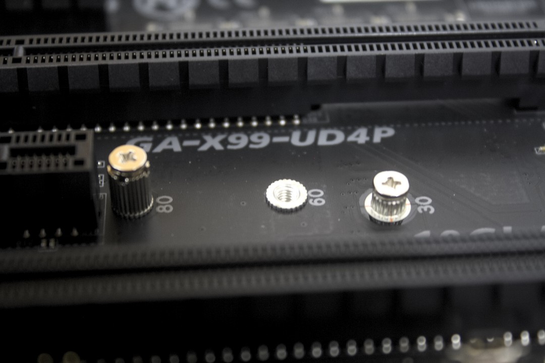
Gigabyte includes two mounting screws that are located just above the two M.2 connectors; these will be needed to secure our M.2 Wi-Fi cards or M.2 SATA Express cards. Keep in mind that if you do plan on using both of these ports, the M.2 Wi-Fi card gets installed first then the SATA Express card.

A closer look at the Realtek Audio controller used on the Gigabyte X99-UD4P motherboard shows us that Gigabyte places 11 capacitors along the side of the main audio controller to help reduce any unwanted interference from the motherboard while listening to our music, movies, or games.
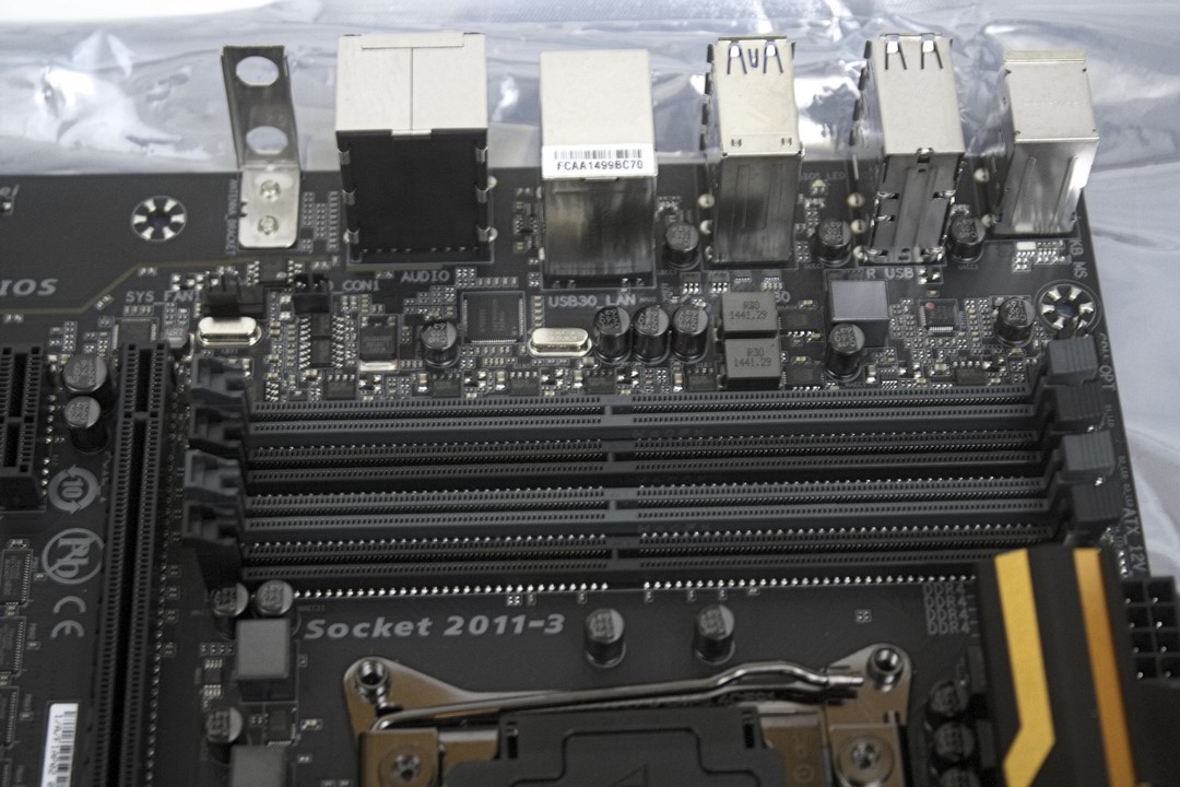
Moving to the area directly in front of the rear I/O ports, there are four memory DIMMs that are placed in between the CPU socket and the rear I/O ports, giving us a total of 8 Memory DIMMs. These 8 DIMM slots will allow us to use up to 64GB of memory, the full amount of memory that a 2011v3 CPU can handle. To the far right hand corner of the picture is an 8-pin EPS power plug on the far edge of the motherboard.
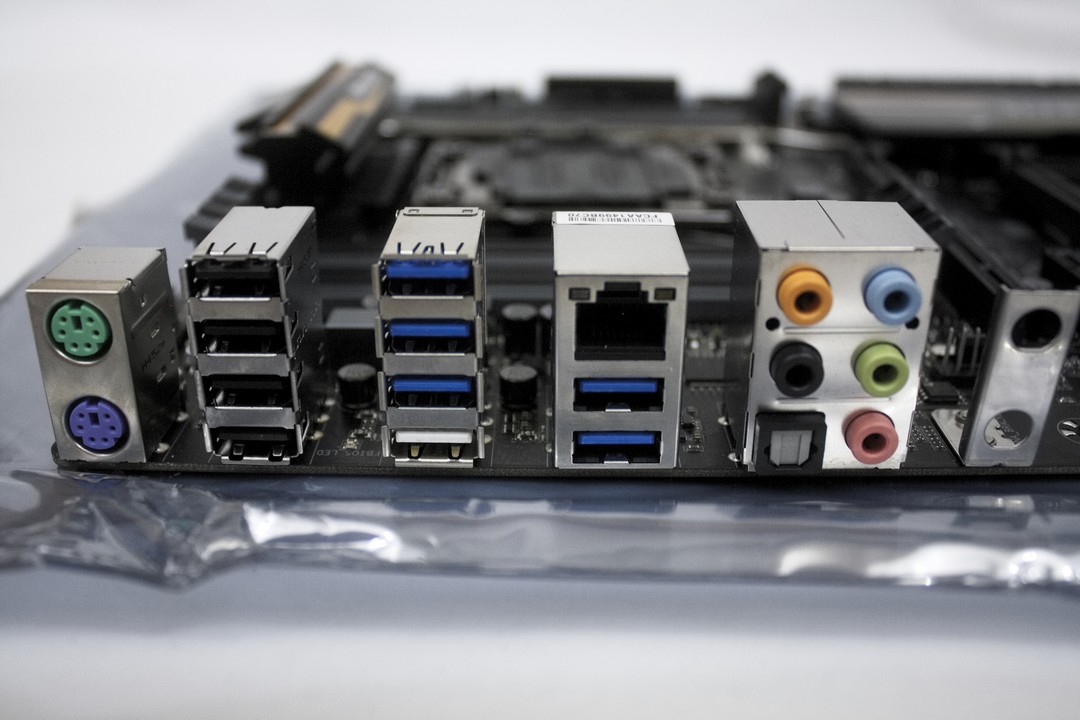
Looking at the rear I/O ports of the motherboard, starting from the left moving right, Gigabyte includes two PS2 keyboard/mouse connectors. I am a bit confused as to why these particular ports have been installed onto this motherboard. I haven’t used PS2 keyboards/mice in years. And, to my knowledge I haven’t seen any newer peripherals use this type of port. Moving to the right, Gigabyte includes four USB 2 ports, followed by four USB 3 ports. The lower white port on this column, the Q-Flash Plus port, is for when we need to flash or to recover the motherboard when we fail a flashing. Moving right again, we get the Intel-based LAN 10/100/1000 Ethernet port, with two more USB 3 ports. At the end on the right are the Realtek Audio outputs. These are in a standardized format, and the on-board sound card is capable of handling a 7.1 audio configuration. Also, there is an optical audio output for those who use this particular port. The farthest right bracket is for our Wi-Fi wires or connector for when we decide to install an M.2 Wi-Fi card onto this motherboard.
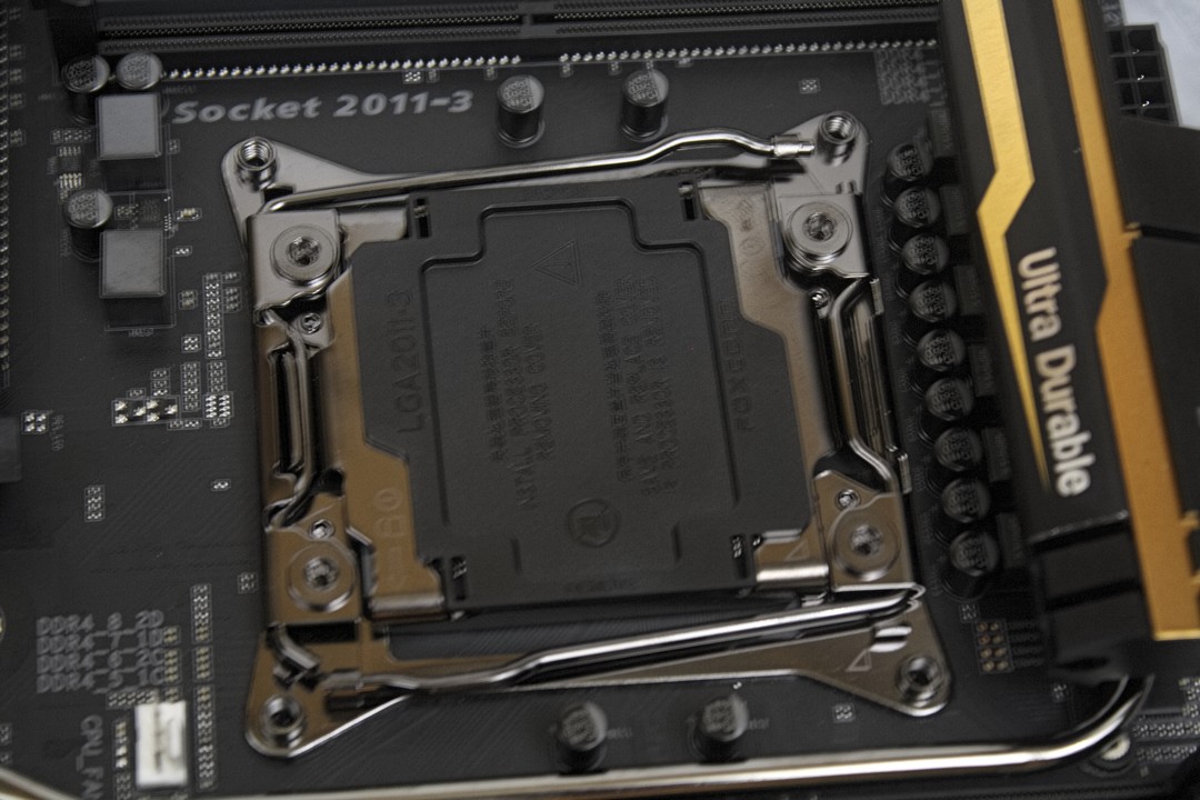
The CPU socket is clear of any large obstacles that could hinder us from using large CPU coolers.
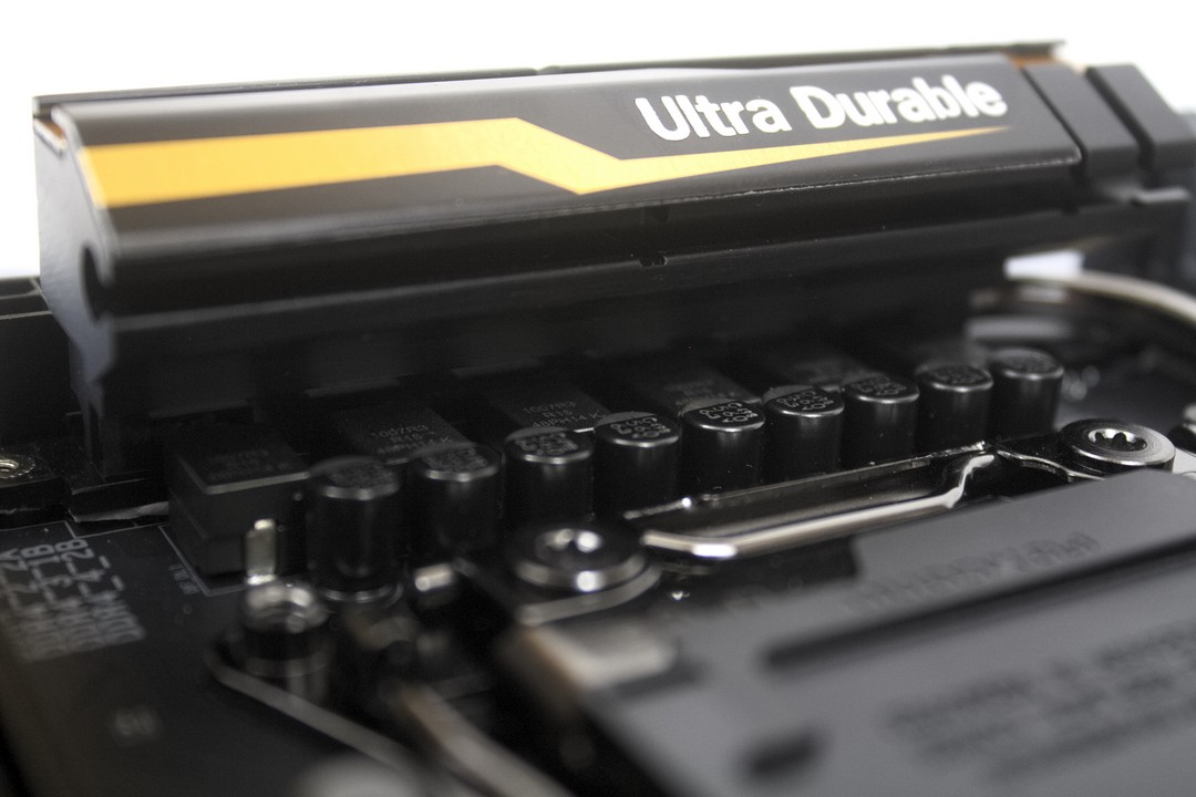
Here we see the large heat sink that Gigabyte employed on the X99-UD4P motherboard to help keep the phased power distribution chips cool during our use of this motherboard. The X99-UD4P motherboard uses a 6 phased power distribution to the CPU.
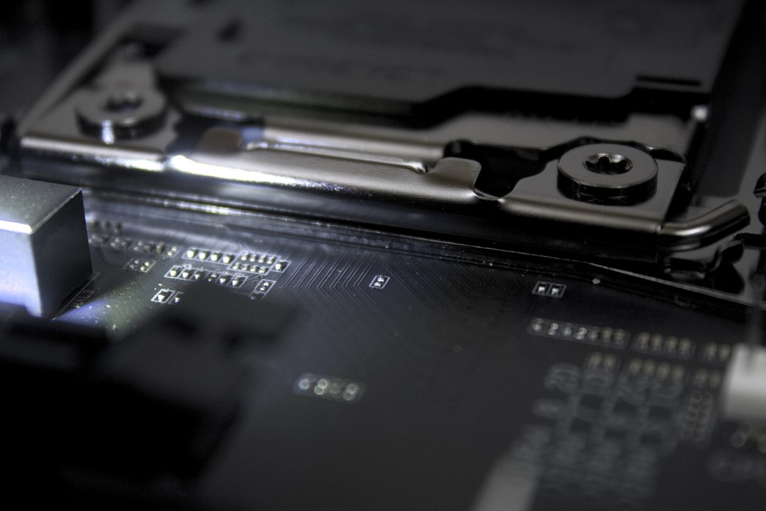
One thing I been seeing on the Internet is that we are no longer able to use back plates on our CPUs, or have our CPU cooling screws go through the motherboard. This next couple of images are there to put to rest that is not the case with the Gigabyte X99-UD4P motherboard. Looking in between the CPU locking mechanism and the motherboard we see a rubber membrane that keeps the metal part of the CPU hold down from contacting the motherboard directly.
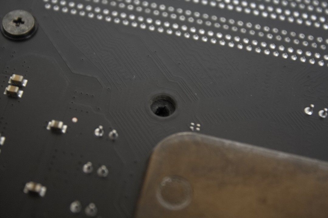
As shown in this image, there are four corresponding holes near the CPU socket area on the backside of the motherboard. All we need to do is be careful and poke a small hole into the rubber membrane so we can use longer screws or a back plate on this motherboard for our heavy CPU coolers. This is completely optional, and at your discretion.
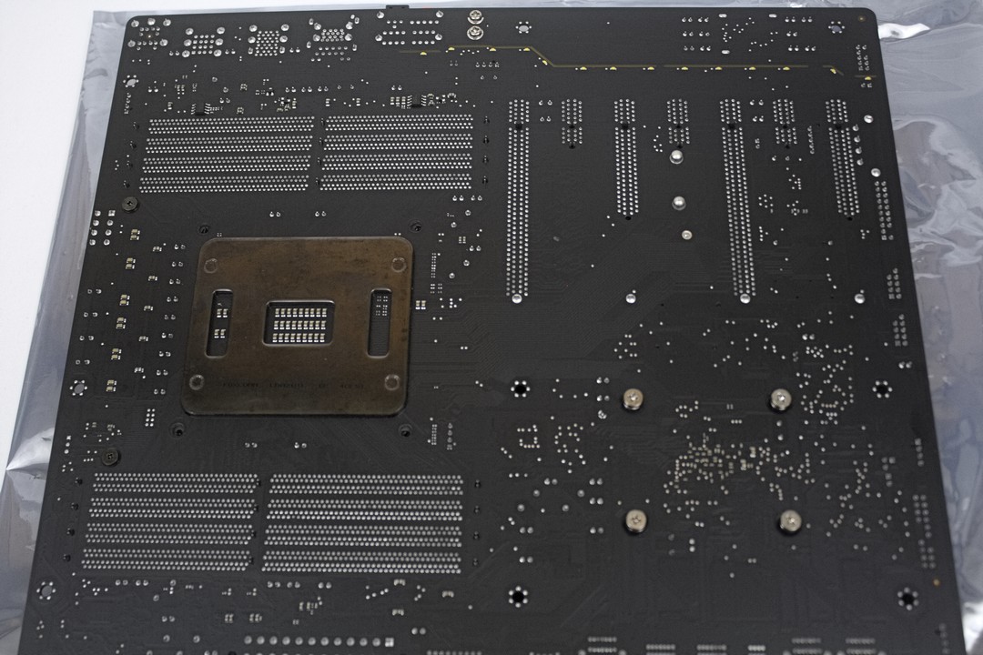
Here is a quick look at the backside of the motherboard.

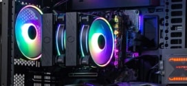
Here is what the Gigabyte UD4P motherboard looks like when it is all hooked up and running. Now if you noticed the area that separates the on-board audio controller from the rest of the motherboard (Right above/behind the PCI expansion ports) there is a small yellow line that is used as a separator. This small line lights up, and we can have this either stay on continuously, beat to our music, or we can turn it off. The PCH heatsink also lights up, and can be turned on continuously, beat to our music, or turned off as well. The rear I/O plate shield lights up as well, but instead of being a yellow/orange shade like the rest of the lights, it glows blue? Things that make you go “Hmm, OT that is rather interesting”. Like the PCH heat sink, and the audio separator line, it too can be turned on continuously, beat to our music, or turned off. We are confused as to why Gigabyte uses blue LEDs on the I/O shield instead of the yellow/orange color scheme they have going on with the rest of this motherboard.