Most of the newer motherboards provide one or more onboard RAID controllers capable of delivering configurations up to and including RAID 5. My goal is to give our readers from beginner to expert a guide that will benefit them.
INTRODUCTION
The use of RAID, a Redundant Array of Inexpensive Disks, up until a few years ago was pretty much limited to servers and high end workstations; this was primarily due to the cost of the controller and the accompanying hard drives. Today that’s not at all the case! Most of the newer motherboards provide one or more onboard RAID controllers capable of delivering configurations up to and including RAID 5. With the cost of disk storage at an all time low the two primary barriers to using this once esoteric form of data storage have been lifted.
Let me state for the record that I know there are a number of quality guides on the Internet covering this subject. My rationale for writing this guide is quite simple, the most recent guide(s) I was able to find was written in 2004, the only exception to this was a white paper article published by California Software Labs in February, 2006. Even though a great deal of the techniques for RAID implementation haven’t changed, much of the equipment has. In 2004 onboard RAID controllers were just beginning to appear, today they’re commonplace and considerably better. In 2004 SATA drives were not the standard as they are today.
My goal is to give our readers from beginner to expert a guide that will benefit them. The beginning users should come away with an understanding of all the intricacies of RAID enabling them to make an informed decision whether RAID is an appropriate modality for their use. The more advanced users should garner additional information helping them decide if moving to a different level of RAID in hopes of reaching some predetermined level of performance or redundant protection is feasible. Most important of all, I want this to be a positive learning experience for both you and me!
Rather than than trying to fix something that’s not broken, I plan through research to take what has already been written, coupled with my own thoughts and experiences and update it to a very thorough, yet easy to read guide to RAID that’s applicable to 2006. Initially I plan for the guide to have two parts. Part 1, will be function and procedure oriented covering the basics of RAID including the history, terminology, types of RAID, functionality, pros and cons, and descriptions. Part 2, will be dedicated solely equipment ranging from on-board chip sets to separate, highly efficient RAID cards for your project ranging from the more cost efficient approach up to unlimited approach. Emphasis here will be limited to a single system and small home networks as larger, enterprise wide networks will exceed the scope of most of our readers.
HISTORY OF RAID
Most credit the beginning of RAID research to Norman Ken Ouchi at IBM. He was issued U.S. Patent 4,092,732 titled “System for recovering data stored in failed memory unit” in 1978 and the claims for this patent describe what would later be termed RAID 5 with full stripe writes. This 1978 patent also mentions that disk mirroring or duplexing (what would later be termed RAID 1) and protection with dedicated parity (what would later be termed RAID 4) were prior art at that time.
RAID levels 1 through 5 were formally defined by David A. Patterson, Garth A. Gibson and Randy H. Katz in the paper, “A Case for Redundant Arrays of Inexpensive Disks (RAID)”. This paper also listed a mathematical calculation that many believe is still accurate today which is used to determine Meant Time To Failure (MTTF), a key factor in a systems’s fault tolerance. While there have been many ground breaking advances in RAID development since this article, one must fully credit these researchers form the University of California at Berkeley as having the paternity rights to what is considered modern day RAID.
While this history is extremely meaningful to the development of modern day RAID, it did not stop there. Annually the RAID Symposia, an international conference which began in 1998 on RAID development is held. Here researchers, developers, and other interested parties from all over the world meet to present and discuss key research oriented information that is instrumental to the continuing development of even more efficient RAID hardware and software for the present and future.
RAID TERMINOLOGY
Prior to jumping into a discussion of RAID and leaving to chance that you have a complete understanding of the terms that will be referred to in this guide; I thought it appropriate to formulate a review of RAID terminology to keep us all on the same page from the beginning. I found the best descriptions of the terms we’ll be using in the glossaries and/or articles provided by GEEK.com, Wikipedia, Webopedia, PC STATS’ Beginners Guides: Installing RAID on Desktop PCs and California Software Labs.
Terms
RAID (Redundant Array of Inexpensive or Independent Drives) – is a technology that uses multiple hard drives to increase the speed of data transfer to and from hard disk storage, and also to provide instant data backup and fault tolerance for any information you might store on a hard drive.
RAID array – A group of hard drives linked together as a single logical drive, connected to one or more hardware RAID controllers, or be attached normally to a computer using a RAID capable operating system, such as Windows XP Professional.
Redundancy – In a redundant system, if you lose part of the system, you can continue to operate. For example, if you have two power supplies and one takes over if the other one dies, that is a form of redundancy. You can take redundancy to extreme levels, but you spend more money.
JBOD (Just a Bunch Of Disks) – One or more disk drives that form a single volume. However, the information on these disks is not striped in any way or protected–a JBOD is not a RAID. The term JBOD can also be used to refer to a volume on a single drive, where anything that’s not a RAID is a JBOD.
Bit – The smallest unit of measure in a computer. It is represented by a 0 (off) or 1 (on). You can think of a bit as a switch. If it’s in the on position it’s a 1, and if the switch is off it’s a 0. All parts of your computer communicate in bits at the lowest level.
Byte – A contiguous sequence of binary bits within a binary computer, that comprises the smallest addressable sub-field of the computer’s natural word-size. That is, the smallest unit of binary data on which meaningful computation, or natural data boundaries, could be applied.
Fault-tolerance – Simply put this is the ability of a RAID array to continue to function after the degradation or loss of one or more of its constituent components.
Hard disk drive (HDD)– is a non-volatile data storage device that stores data on a magnetic surface layered onto hard disk platters.
Volume– A fixed amount of storage on a disk or tape. The term volume is often used as a synonym for the storage medium itself, but it is possible for a single disk to contain more than one volume or for a volume to span more than one disk.
Disk Mirroring – A procedure in which data sent to a RAID array is duplicated and written onto two or more drives at once.
Disk Duplexing– A procedure much like disk mirroring, but each drive is on a separate controller. This speeds up the normally slow write operations and also adds an additional level of redundancy, in case one of your controller cards dies.
Striping – A procedure in which data sent to a RAID array is broken down and portions of it written to each drive in the array. This can dramatically speed up hard drive access when the data is read back, since each drive can transfer part of the data simultaneously.
Parity– In its simplest form, parity is an addition of all the drives used in an array. Recovery from a drive failure is achieved by reading the remaining good data and checking it against parity data stored by the array. Parity is used by RAID levels 2, 3, 4, and 5. RAID 1 does not use parity because all data is completely duplicated (mirrored). RAID 0, used only to increase performance, offers no data redundancy at all.
Mean Time to Data Loss (MTDL)– The average time before the failure of an array component causes data to be lost or corrupted.
Mean Time between Data Access / Availability (MTDA)– The average time before non-redundant components fail, causing data inaccessibility without loss or corruption.
Mean Time To Repair (MTTR)– The average time required to bring an array storage subsystem back to full fault tolerance.
Mean Time Between Failure (MTBF)– Used to measure computer component average reliability/life expectancy. MTBF is not as well-suited for measuring the reliability of array storage systems as MTDL, MTTR or MTDA because it does not account for an array’s ability to recover from a drive failure. In addition, enhanced enclosure environments used with arrays to increase uptime can further limit the applicability of MTBF ratings for array solutions.
SOFTWARE VS. HARDWARE RAID
From this point onward in this guide much of the information was either directly adapted from or quoted from a white paper entitled “Redundant Array of Inexpensive Disks (RAID)” published by California Software Labs in February, 2006. All images were developed by this author.
Software based RAID
Primarily used with entry-level servers, software-based arrays rely on a standard host adapter and execute all I/O commands and mathematically intensive RAID algorithms in the host server CPU. This can slow system performance by increasing host PCI bus traffic, CPU utilization, and CPU interrupts. Some NOSs such as NetWare, Windows NT, and Windows XP (non NOS). include embedded RAID software. The chief advantage of this embedded RAID software has been its lower cost compared to higher-priced RAID alternatives. However, this advantage is disappearing with the advent of lower-cost, bus-based array adapters. The major advantages are low-cost & it requires only a standard controller.
Hardware based RAID
Unlike software-based arrays, bus-based array adapters/controllers plug into a host bus slot (typically a 133 MByte (MB)/sec PCI bus) and offload some or all of the I/O commands and RAID operations to one or more secondary processors. Originally used only with mid- to high-end servers due to cost, lower-cost bus-based array adapters are now available specifically for entry-level server network applications.
In addition to offering the fault-tolerant benefits of RAID, bus-based array adapters /controllers perform connectivity functions that are similar to standard host adapters. By residing directly on a host PCI bus, they provide the highest performance of all array types. Bus-based arrays also deliver more robust faulttolerant features than embedded NOS RAID software.
Advantages are data protection & performance benefits of RAID and more robust fault-tolerant features and increased performance versus software-based RAID.
External Hardware RAID Card
Intelligent external array controllers bridge between one or more server I/O interfaces and Single / multiple-device channels. These controllers feature an onboard microprocessor, which provides high performance and handles functions such as executing RAID software code and supporting data caching.
External array controllers offer complete operating system independence, the highest availability, and the ability to scale storage to extraordinarily large capacities (up to a terabyte and beyond). These controllers are usually installed in networks of stand-alone Intel-based and UNIX-based servers as well as clustered server environments.
Advantages are OS independent and to build super high-capacity storage systems for high-end servers.
RAID LEVELS 0 & 1
There are several different RAID levels or redundancy schemes, each with an inherent cost, performance, and availability (fault-tolerance) characteristics designed to meet different storage needs. No individual RAID level is inherently superior to any other. Each of the five array architectures is well-suited for certain types of applications and computing environments. For client/server applications, storage systems based on RAID levels 1, 0/1, and 5 have been the most widely used.
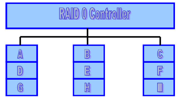
RAID Level 0 (Non-Redundant)
A non-redundant disk array, or RAID level 0, has the lowest cost of any RAID organization because it does not employ redundancy at all. This scheme offers the best write performance since it never needs to update redundant information but it does not have the best read performance. Redundancy schemes that duplicate data, such as mirroring, can perform better on reads by selectively scheduling requests on the disk with the shortest expected seek and rotational delays. Without, redundancy, any single disk failure will result in data-loss. Non-redundant disk arrays are widely used in super-computing environments where performance and capacity, rather than reliability, are the primary concerns.
Sequential blocks of data are written across multiple disks in stripes. The size of a data block, which is known as the stripe width, varies with the implementation, but is always at least as large as a disk’s sector size. When it comes time to read back this sequential data, all disks can be read in parallel. In a multi-tasking operating system, there is a high probability that even non-sequential disk accesses will keep all of the disks working in parallel.
Minimum number of drives: 2
Strengths: Highest performance
Weaknesses: No data protection; One drive fails, all data is lost
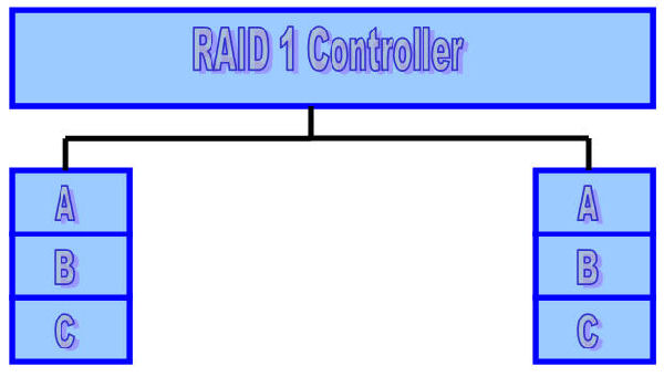
RAID Level 1 (Mirrored)
The traditional solution, called mirroring or shadowing, uses twice as many disks as a non-redundant disk array. Whenever data is written to a disk the same data is also written to a redundant disk, so that there are always two copies of the information.When data is read, it can be retrieved from the disk with the shorter queuing, seek and rotational delays. If a disk fails, the other copy is used to service requests. Mirroring is frequently used in database applications where availability and transaction time are more important than storage efficiency.
Minimum number of drives: 2
Strengths: Very high performance; Very high data protection; Very minimal penalty on write performance.
Weaknesses: High redundancy cost overhead; Because all data is duplicated, twice the storage capacity is required.
RAID LEVELS 2 & 3
RAID Level 2 (Memory Style)
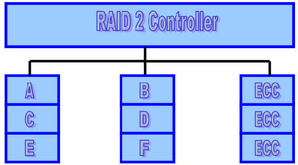
Memory systems have provided recovery from failed components with much less cost than mirroring by using Hamming codes. Hamming codes contain parity for distinct overlapping subsets of components. In one version of this scheme, four disks require three redundant disks, one less than mirroring. Since the number of redundant disks is proportional to the log of the total number of the disks on the system, storage efficiency increases as the number of data disks increases.
If a single component fails, several of the parity components will have inconsistent values, and the failed component is the one held in common by each incorrect subset. The lost information is recovered by reading the other components in a subset, including the parity component, and setting the missing bit to 0 or 1 to create proper parity value for that subset. Thus, multiple redundant disks are needed to identify the failed disk, but only one is needed to recover the lost information.
In you are unaware of parity, you can think of the redundant disk as having the sum of all data in the other disks. When a disk fails, you can subtract all the data on the good disks form the parity disk; the remaining information must be the missing information. Parity is simply this sum modulo 2.
A RAID 2 system would normally have as many data disks as the word size of the computer, typically 32. In addition, RAID 2 requires the use of extra disks to store an error-correcting code for redundancy. With 32 data disks, a RAID 2 system would require 7 additional disks for a Hamming-code ECC.
For a number of reasons, including the fact that modern disk drives contain their own internal ECC, RAID 2 is not a practical disk array scheme.
Minimum number of drives: Not used in LAN
Strengths: Previously used for RAM error environments correction (known as Hamming Code ) and in disk drives before he use of embedded error correction.
Weaknesses: No practical use; Same performance can be achieved by RAID 3 at lower cost.
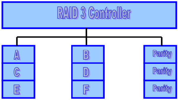
RAID Level 3 (Bit-Interleaved Parity)
One can improve upon memory-style ECC disk arrays by noting that, unlike memory component failures, disk controllers can easily identify which disk has failed. Thus, one can use a single parity rather than a set of parity disks to recover lost information.
In a bit-interleaved, parity disk array, data is conceptually interleaved bit-wise over the data disks, and a single parity disk is added to tolerate any single disk failure. Each read request accesses all data disks and each write request accesses all data disks and the parity disk. Thus, only one request can be serviced at a time. Because the parity disk contains only parity and no data, the parity disk cannot participate on reads, resulting in slightly lower read performance than for redundancy schemes that distribute the parity and data over all disks. Bit-interleaved, parity disk arrays are frequently used in applications that require high bandwidth but not high I/O rates. They are also simpler to implement than RAID levels 4, 5, and 6.
Here, the parity disk is written in the same way as the parity bit in normal Random Access Memory (RAM), where it is the Exclusive Or of the 8, 16 or 32 data bits. In RAM, parity is used to detect single-bit data errors, but it cannot correct them because there is no information available to determine which bit is incorrect. With disk drives, how ever, we rely on the disk controller to report a data read error.Knowing which disk’s data is missing, we can reconstruct it as the Exclusive Or (XOR) of all remaining data disks plus the parity disk.
Minimum number of drives: 3
Strengths: Excellent performance for large, sequential data requests.
Weaknesses: Not well-suited for transaction-oriented network applications; Single parity drive does not support multiple, simultaneous read and write requests.
RAID LEVELS 4 & 5
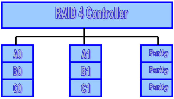
RAID Level 4 (Block-Interleaved Parity)
The block-interleaved, parity disk array is similar to the bit-interleaved, parity disk array except that data is interleaved across disks of arbitrary size rather than in bits.The size of these blocks is called the striping unit. Read requests smaller than the striping unit access only a single data disk. Write requests must update the requested data blocks and must also compute and update the parity block. For large writes that touch blocks on all disks, parity is easily computed by exclusive-or’ing the new data for each disk. For small write requests that update only one data disk, parity is computed by noting how the new data differs from the old data and applying those differences to the parity block. Small write requests thus require four disk I/Os: one to write the new data, two to read the old data and old parity for computing the new parity, and one to write the new parity. This is referred to as a read-modify-write procedure. Because a block-interleaved, parity disk array has only one parity disk, which must be updated on all write operations, the parity disk can easily become a bottleneck. Because of this limitation, the block-interleaved distributed parity disk array is universally preferred over the block-interleaved, parity disk array.
A write request for one block is issued by a program:
- The RAID software determines which disks contain the data, and parity, and which block they are in.
- The disk controller reads the data block from disk.
- The disk controller reads the corresponding parity block from disk.
- The data block just read is XORed with the parity block just read.
- The data block to be written is XORed with the parity block.
- The data block and the updated parity block are both written to disk.
It can be seen from the above example that a one block write will result in two blocks being read from disk and two blocks being written to disk. If the data blocks to be read happen to be in a buffer in the RAID controller, the amount of data read from disk could drop to one, or even zero blocks, thus improving the write performance.
Minimum number of drives:3 (Not widely used)
Strengths: Data striping supports multiple simultaneous read requests.
Weaknesses: Write requests suffer from same single parity-drive bottleneck as RAID 3; RAID 5 offers equal data protection and better performance at same cost. For small writes, the performance will decrease considerably. To understand the cause for this, a one-block write will be used as an example.
RAID Level 5 (Block-Interleaved Distributed Parity)
The block-interleaved distributed-parity disk array eliminates the parity disk bottleneck present in the block-interleaved parity disk array by distributing the parity uniformly over all of the disks. An additional, frequently overlooked advantage to distributing the parity is that it also distributes data over all of the disks rather than over all but one. This allows all disks to participate in servicing read operations in contrast to redundancy schemes with dedicated parity disks in which the parity disk cannot participate in servicing read requests. Block-interleaved distributed-parity disk array have the best small read, large write performance of any redundancy disk array. Small write requests are somewhat inefficient compared with redundancy schemes such as mirroring however, due to the need to perform read-modify-write operations to update parity. This is the major performance weakness of RAID level 5 disk arrays.
The exact method used to distribute parity in block-interleaved distributed-parity disk arrays can affect performance. The following figure illustrates left-symmetric parity distribution.
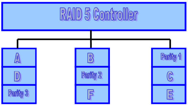
Each square corresponds to a stripe unit. Each column of squares corresponds to a disk. Parity 1 computes the parity over stripe units A and B; Parity 2 computes parity over stripe units C and D; Parity 3 computes the parity over stripe units E and F.
A useful property of the left-symmetric parity distribution is that whenever you traverse the striping units sequentially, you will access each disk once before accessing any disk device. This property reduces disk conflicts when servicing large requests.
Minimum number of drives: 3
Strengths: Best cost/performance for transaction-oriented networks; Very high performance, very high data protection; Supports multiple simultaneous reads and writes; Can also be optimized for large, sequential requests.
Weaknesses: Write performance is slower than RAID 0 or RAID 1.
RAID LEVELS 6 & 10
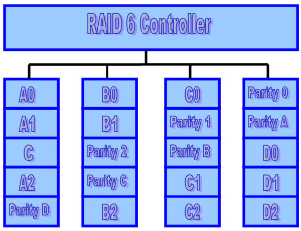
RAID Level 6 (P+Q Redundancy)
Parity is a redundancy code capable of correcting any single, self-identifying failure.As large disk arrays are considered, multiple failures are possible and stronger codes are needed. Moreover, when a disk fails in parity-protected disk array, recovering the contents of the failed disk requires successfully reading the contents of all non-failed disks. The probability of encountering an uncorrectable read error during recovery can be significant. Thus, applications with more stringent reliability requirements require stronger error correcting codes.
Once such scheme, called P+Q redundancy, uses Reed-Solomon codes to protect against up to two disk failures using the bare minimum of two redundant disk arrays. The P+Q redundant disk arrays are structurally very similar to the blockinterleaved distributes-parity disk arrays and operate in much the same manner. In particular, P+Q redundant disk arrays also perform small write operations using a read-modify-write procedure, except that instead of four disk accesses per write requests, P+Q redundant disk arrays require six disk accesses due to the need to update both the `P’ and `Q’ information.
RAID Level 10 (Striped Mirrors)
RAID 10 is now used to mean the combination of RAID 0 (striping) and RAID 1 (mirroring). Disks are mirrored in pairs for redundancy and improved performance, and then data is striped across multiple disks for maximum performance.
RAID 10 uses more disk space to provide redundant data than RAID 5. However, it also provides a performance advantage by reading from all disks in parallel while eliminating the write penalty of RAID 5. In addition, RAID 10 gives better performance than RAID 5 while a failed drive remains un-replaced. Under RAID 5, each attempted read of the failed drive can be performed only by reading all of the other disks. On RAID 10, a failed disk can be recovered by a single read of its mirrored pair.
Minimum number of drives: 4
Strengths: Highest performance, highest data protection (can tolerate multiple drive failures).
Weaknesses: High redundancy cost overhead; Because all data is duplicated, twice the storage capacity is required; Requires minimum of four drives.
COMPOUND RAID LEVELS
There are times when more then one type of RAID must be combined, in order to achieve the desired effect. In general, this would consist of RAID-0, combined with another RAID level. The primary reason for combining multiple RAID architectures would be to get either a very large, or a very fast, logical disk. The list below contains a few examples. It is not the limit of what can be done.
RAID-1+0
RAID Level 1+0 (also called RAID-10) is the result of RAID-0 applied to multiple RAID-1 arrays. This will create a very fast, stable array. In this array, it is possible to have multiple disk failures, without losing any data, and with a minimum performance impact. To recover from a failed disk, it is necessary to replace the failed disk, and rebuild that disk from its mirror. For two-drive failures, the probability of survival is 66% for a 4-disk array, and approaches 100% as the number of disks in the array increases.
RAID-0+1
RAID Level 0+1 is the result of RAID-1 applied to multiple RAID-0 arrays. This will create a very fast array. If the RAID-0 controllers (hardware or software) are capable of returning an error for data requests to failed drives, then this array has all the abilities of RAID-10. If an entire RAID-0 array is disabled when one drive fails, this becomes only slightly more reliable then RAID-0.
To recover from a failed disk, it is necessary to replace the failed disk, and rebuild the entire RAID-0 array from its mirror. This requires much more disk I/O than is required to recover from a disk failure in RAID-10. It should be noted that some enterprise-level RAID controllers are capable of tracking which drives in a RAID-0 array have failed, and only rebuilding that drive. These controllers are very expensive.
For two-drive failures, the probability of survival is 33% for a 4-disk array, and approaches 50% as the number of disks in the array increases. This RAID level is significantly less reliable than RAID-1+0. This is because the structure is inherently less reliable in a multi-disk failure, combined with the longer time to reconstruct after a failure (due to a larger amount of data needing to be copied).
The longer time increases the probability of a second disk failing before the first disk has been completely rebuilt.
RAID-3+0
RAID Level 3+0 is the result of RAID-0 applied to multiple RAID-3 arrays. This will improve the performance of a RAID-3 array, and allow multiple RAID-3 arrays to be dealt with as a single logical device. RAID-3+0 has reliability similar to RAID-3, with improved performance. This type of array is most commonly found when combining multiple hardware RAID devices into a single logical device.
RAID-5+0
RAID Level 5+0 (also called RAID-53 for some unknown reason) is the result of RAID-0 applied to multiple RAID-5 arrays. This will improve the performance of a RAID-5 array, and allow multiple RAID-5 arrays to be dealt with as a single logical device. The reliability of this type of array is similar to that of a RAID-1+0 array, but it has the performance impacts of RAID-5. This type of array is most commonly found when combining multiple hardware RAID devices into a single logical device.
SUMMARY
Being a System Administrator for a huge enterprise-wide, Oracle-based, healthcare related database that’s nested in over 25 Linux based servers to enable load balancing; I thought I had a pretty good understanding of RAID and its constituent elements. Man was I wrong! Doing the research for this article was a huge learning opportunity, especially when it comes to the less used but still readily available forms of RAID. It is my sincere hope that you enjoy reading this guide as much as I did writing it.
Remember, this is only Part 1 of this article! Part 2 which I hope to have ready to publish in the next month or so will look at not only the onboard controllers that many of you are currently using, but also at a number of the hardware RAID cards that are currently available. We will explore what we hope is the essential information to help you make the best informed decision possible when it comes to the subject of RAID.