With a name like Maximus Extreme you’d better be ready to walk the walk. Does Asus have what it takes with their newest offering built atop the X38 chipset or is it all show and no go?
INTRODUCTION
Ferrari automobiles, Rolex watches and Brioni suits. Each of these items commands respect in their individual fields. Standing as the pinnacle of engineering, each of these products fetch a high premium but with that premium comes the satisfaction of knowing you are getting the very best. While they may not be the most practical choices for one reason or another, they deliver on their promise of quality. Which brings me to the Maximus Extreme, a motherboard that offers the very latest in features and options. Keeping the enthusiast in mind, this motherboard was not designed for a casual gamer or even a hard-core gamer who only loves to play. No. This board was designed for those of us who must tweak and fiddle endlessly, eek out every last MHz of performance. Is it practical? Much like a Ferrari, there are cheaper ways to get to the store but this is the one we all dream about. So come with me as I dive deep into the inner workings of the Maximus Extreme and try to uncover the true potential of this board. And if nothing else, you get to use the line ‘I have a Maximus, what do you have?’
ASUS: The Company

ASUS, a technology-oriented company blessed with one of the world’s top R&D teams, is well known for high-quality and innovative technology. As a leading provider of 3C (computers, communications and consumer electronics) total solutions, ASUS offers a complete product portfolio to compete in the new millennium.
In 2005, ASUS shipped 52 million motherboards, which means one out of every 3 desktop PCs sold that year was powered by an ASUS motherboard. If we line them up side by side, the length will be longer than the distance from New York to San Francisco.
ASUS products’ top quality stems from product development. It’s like learning Chinese Kung-Fu; one must begin with cultivating the “Chi” and inner strength. Besides innovating cutting-edge features, ASUS engineers also pay special attention to EMI (electromagnetic interference), thermal, acoustics and details that usually go unnoticed to achieve complete customer satisfaction. ASUS notebooks are the first TCO’99-certified notebooks worldwide. The requirements for this honor include radiation emission control, energy (battery consumption), ecology (environment friendly) and ergonomics.
Imagine innovations that simplify our lives and enable us to realize our full potential. It is technologies’ responsibility to accommodate us, not the other way around, because all devices should perform and communicate seamlessly anytime, anywhere. ASUS thrives to become an integrated 3C solution provider. (Computer, Communications, Consumer electronics.)
Over the past 2 decades, technology has changed the way we live and experience the world. We have been enabled to work, play, learn, and communicate in ways we have never before thought possible. Since its inception, ASUS has been the cornerstone of this evolution. 1 out of every 4 desktop PCs in the world today has an ASUS motherboard inside. As a major player of this evolution, we have established our corporate mission … ASUS mission: Provide innovative IT solutions that empower people and businesses reaching their full potential.
FEATURES AND SPECIFICATIONS
Performance
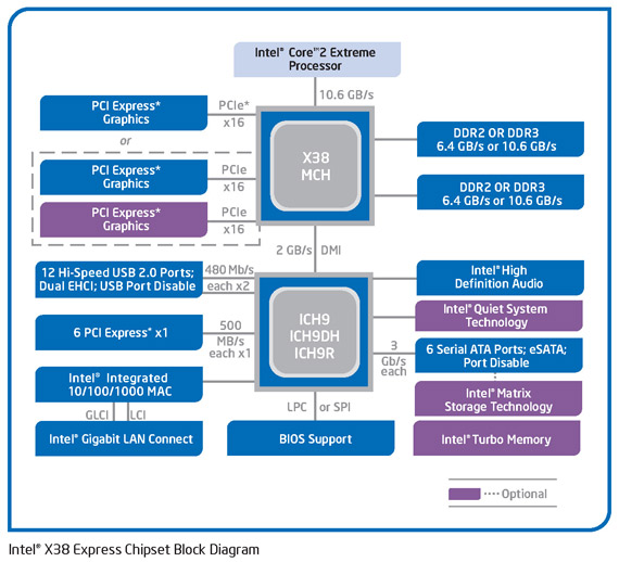
Based on Intel X38 Chipset
Supports Intel Core 2 Extreme, Core 2 Quad, Core 2 Duo, Pentium and upcoming 45nm CPUs
800/1066/1333/1600 Mhz Front Side Bus
Chipset
Northbridge: Intel© X38
Southbridge: Intel© ICH9R
Memory
4 x DIMM, max. 8GB, 1800(O.C)/1600(O.C.)/1333/1066
Dual Channel architecture
Supports Intel® XMP Technology
Expansion Slots
3 x PCIe x16 (support dual PCIe2.0 x16 or 1x PCIe2.0 x16, dual x8 speed)
2 x PCIe x1
2 x PCI 2.2
Storage I/O
Southbridge
- 1 x Floppy disk drive connector
- 6 x SATA-II 300MB/sec
- Intel Matrix Storage Technology supports RAID 0, 1, 5 and 10
JMicron® JMB363 PATA and SATA controller
- 2 x External SATA 3.0 Gb/s port (SATA On-the-Go)
- 1 x UltraDMA 133/100/66 for up to 2 PATA devices
Audio
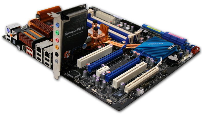
SupremeFX II Audio Card
- ADI 1988B 8-channel High Definition Audio CODEC
- Noise Filter
Coaxial, Optical S/PDIF out at back I/O
LAN
Dual Gigabit LAN controllers, both featuring AI NET2 Support Teaming Technology
Multi I/O
1 x PS2 Keyboard
1 x Clr CMOS switch
2 x RJ-45 Port
2 x External SATA
2 x IEEE 1394 Ports (1 port at back I/O, 1 port onboard)
2 x SPDIF out port ( 1 x Coaxial, 1 x Optical S/PDIF)
6 x Audio connector (Center speaker/Subwoofer Out, Rear speaker out, Side speaker out, Line-in, Line-out, MIC)
12 x USB 2.0 ports (6 rear + 6 internal headers)
Form Factor
ATX Form Factor
Length: 12.0in – 305mm
Width: 10.6in – 269mm*
* It is important to note that this board uses standard ATX mounting holes but is one inch longer than the standard spec. This could cause installation issues with smaller cases.
PACKAGING
Asus packages this board very well right down to the clear plastic shell that encases it. The front and rear of the box are full of photos and awards. So much so, that Asus had to add a flap to the front cover of the box in order to fit all the features and awards. Even the accessories of the Maximus Extreme are given some VIP treatment with their very own box.
Click a picture to see a larger view
 |
 |
 |
 |
 |
CONTENTS
Continuing with the high-end theme of the board, Asus included every accessory an enthusiast would need to get this board up and running. The package include six SATA cables, rear USB/Firewire bracket, FDD cable, ATA cable, three thermocouples, rear I/O shield that lights up, driver CD, optional fan for the North Bridge, LCD BIOS poster, manual, zip ties, clamps for the fusion block and even a free game.
When a component, any component, costs more than the average component of its type you should expect a well rounded bundle and that is just what Asus gives you.
Click a picture to see a larger view
 |
 |
LAYOUT
| Layout | |
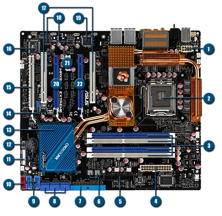
| 1. 8-pin 12 volt socket | 12. Clear CMOS Switch |
| 2. LGA 775 CPU Socket | 13. Heat sink for Crosslink & South Bridge |
| 3. Four Dual-Channel DDR3 slots | 14. USB pin-out (Two ports) |
| 4. 24-pin ATX socket | 15. PCI Express 1.1 x16 slot (x8 electrical) |
| 5. Floppy drive connector | 16. VIA 6308P IEEE1394a Firewire |
| 6. On-board Power & Reset switch | 17. Two PCI slots |
| 7. IDE connector | 18. Two Marvell PCI Express Gigabit Ethernet |
| 8. Six SATA-II ports | 19. J-Micron JMB363 |
| 9. USB pin-out (Four ports) | 20. PCI Express 2.0/1.1 x16 slot (x16/x8 electrical) |
| 10. Firewire pin-out | 21. PCI Express x1 slot |
| 11. Front panel connector | 22. PCI Express 2.0 x16 slot (x16 electrical) |
Before continuing I think it is worth explaining in detail how the PCIe slots on this board work as it is not as straight forward as you might think. If you use two video cards in Crossfire mode in the blue PEG slots then you will receive the full benefits of PCIe 2.0 x16 bandwidth and the world will be your oyster. If you decide, however, you want to toss in a third video card or any PCIe compatible card for that matter (i.e. RAID card, sound card, etc) in the white slot then the situation becomes somewhat less pleasant.
The white PCIe slot runs at x8 speeds with PCIe 1.1 specifications. Using this slot causes the secondary PEG slot to be downgraded from a x16 slot to a x8 slot. Even worse is that the secondary PEG slot is downgraded further from PCIe 2.0 to PCIe 1.1 bandwidth. This is due to the Crosslink digital PCIe switch Asus uses on the board. It is not compatible with PCIe 2.0 yet. The primary slot is left untouched and this whole point is rather moot at this time since the majority of user have one video card. Those who do dabble in Crossfire have two cards which still affords you the most bandwidth possible as long as the white PCIe slot is left unused. The tiny fraction of you that are left who intend to run Tri-Fire should be aware of the complications you are likely to encounter.
PCIe 2.0 bandwidth operates at 500 MB/s per lane (x16 = 8 GB/s in each direction).
PCIe 1.1 bandwidth operates at 250 MB/s per lane (x16 = 4 GB/s in each direction).
REAR I/O
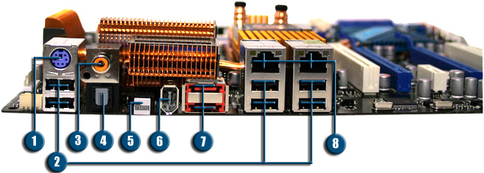
- PS/2 Port – Single connection for a keyboard.
- USB 2.0 Ports – Six ports to connect newer mice and keyboards as well as digital cameras, printers and external drives.
- S/PDIF Out Port – Provides digital audio out to an external audio system that supports digital coaxial audio.
- Optical Out Port – Provides digital audio out to an external audio system that supports digital optical audio.
- CLR CMOS – Used to reset BIOS settings in the case of a failed overclock. (Must enable the CMOS switch on the motherboard first).
- IEEE 1394a Port– Firewire port used to connect various A/V products needing a high-speed path.
- eSATA Ports – Two ports for connecting external hard drives through an ultra fast connection up to 300MB/s.
- Ethernet Ports – Two ports for access to the internet or to setup a home network. Supports speeds up to 1Gbit (1 Gbit = 1000 Mbit)
PHOTO SHOOT
The first image in our photo shoot is crammed with feature. We see the four DDR3 slots that are positioned lower on the board than usual. This helps to maintain a better signal integrity and while the slots are close to the primary PCIe slot, as we will see in a later photo, they do not interfere with the video card. Also in this photo we see on-board power and reset switches which are a huge convenience for anyone who likes to setup their motherboard outside of a case. We also catch a glimpse of the ATX power connector, fusion block system, and CPU socket.
In the second photo below we see a close up of the heat sink for what Asus calls their Crosslink system. The Crosslink system is what enables additional PCIe lanes for those of you who would like to run triple crossfire. Beware though as running triple crossfire will cause the second slot to run as a PCIe 1.0 x8 slot and the last slot will also run as a PCIe 1.0 x8. If you choose to run two cards in crossfire mode (using the blue slots) then you will treated to full PCIe 2.0 x16 slots. The heat sink is only so large because the South Bridge and the Crosslink chip are not located directly next to each other.
Last photo here shows the CMOS battery, front panel connectors and the switch to enable the user to reset BIOS settings with the push of a button. No more trying to pop out the CMOS battery to enable a reset. Now all that needs to be done is to enable the reset switch and push the button. Simple.
Click a picture to see a larger view
 |
 |
 |
 |
 |
 |
Our first image in the second set shows off the board’s six SATA slots, USB connectors, Firewire connector and the only ATA connector. I like how compact the slots are arranged with the ninety degree bend. The only issue I have here is with the amount of connectors. Six SATA connectors would have been plenty a couple of years ago, but with the falling prices of hard drives and optical drives, making the switch to SATA can quickly fill up the six ports on this board.
The last two photos show off the CPU socket area and the fusion block system. The CPU socket area is a bit cluttered though for the amount of cooling and capacitors crammed into this section of the board. Asus did a good job of making the best of a tough situation. The fusion block system is a clever method for appealing to people who like to water cool their board without leaving people who prefer air cooling out in the cold. By itself it will keep the North Bridge cool with only a small amount of airflow, crank up the FSB and you have the option of slapping on some water cooling to keep all that heat in check.
All in all, the features Asus crammed onto this board are pretty good for those who crave the newest technology and like to tinker. Of course if you are the kind of person who prefers to buy a good motherboard and get right to gaming then this board will most likely be overkill.
BIOS
Main Page
This is your basic main page. Here you can setup your hard drives, date, time, and floppy drive.
Extreme Tweaker
This is the page for the overclocker inside us all. You can adjust every voltage and megahertz from this page. The first item, CPU Level UP, is Asus’ attempt at making overclocking a snap. You can select a CPU from the menu, i.e. E6850, E6400, etc, and the board will adjust the voltages and bus speeds accordingly. An interesting innovation but for an control freak like myself I like the idea of adjusting the settings manually. This is one of those ‘wild card’ features. If you’re a hard-core techie then this feature is a waste since you will tweak the board yourself. If you are a new comer to overclocking then this is not the board you would want to start with. Why? With maximum voltages of 2.3 volts for the CPU and 3.04 volts for the DDR3 memory, it is easy to imagine someone going too far to achieve that awesome overclock. Speaking of overclocking, this is the page to adjust various voltages, speeds and timings which become available only after selecting the ‘Manual’ option from the Ai Overclock Tuner. This allows the page to show only the settings required by the user.
Extreme Tweaker (Continued)
The last image in our series here shows the rest of the page as it looks with everything set to auto. Changing different settings to manual allows additional adjustments to be made.
Click a picture to see a larger view
 |
 |
 |
| Main Page | Extreme Tweaker | Extreme Tweaker Cont. |
Advanced Page
At this page we can adjust CPU features, USB settings, onboard functions of the motherboard, and Plug & Play settings.
CPU Configuration
Here you can adjust the CPU multiplier along with other power saving features of the processor. Some of the these include Intel’s SpeedStep and C1E Support.
Onboard Device Configuration
On this page you have the ability to enable/disable the onboard sound, the J-Micron PATA/SATA controller, and both network ports among other things. Also, you can adjust some settings of the LCD poster here as well and even turn off the Republic Of Gamers (ROG) logo light on the motherboard.
USB Configuration
This page pertains to everything USB. Adjusting controller speed, enabling/disabling USB functions, and even setting up a USB mass storage device.
Click a picture to see a larger view
 |
 |
| Advanced Page | CPU Configuration |
 |
 |
| Onboard Device Configuration | USB Configuration |
Power Page
On this page you can adjust the suspend modes of the motherboard, the Advanced Power Management (APM) settings, and monitor various temperatures and voltages.
Hardware Monitor
This is where you can check the temperatures of various components around the board. If you installed the optional thermal probes you can view their readings here as well. Adjustments for thermal protection levels can be set here along with fan settings.
Hardware Monitor Continued
At the bottom of the page we see the voltages listed here for various components. This will give you a rough estimate of the power levels being used by the different parts of the board. I say rough because while these readings come straight from the BIOS, they are still software related. If you experience any power related issues you should always check the voltage levels with a hardware monitoring device.
Click a picture to see a larger view
 |
 |
 |
| Power Page | Hardware Monitor | Hardware Monitor Cont. |
Boot Page
This page is reserved for setting up, among other things, the order in which your drives are selected for the boot process. You can also setup a password here, both for the boot process and to access the BIOS.
Boot Settings Configuration
Turn off the full screen logo during boot, enable/disable fast boot, enable the num-lock key during boot, and have the PC wait for input (F1 key) if there is an error are just some of the settings this page offers.
Tools Page
Here you can set up different profiles for overclocking or even enable the flash utility to update the BIOS itself.
|
|
|
| Boot Page | Boot Settings Configuration | Tools Page |
| Frequency Adjustments | ||
| Adjustment | Range (In MHz) | Increment (In MHz) |
| Front Side Bus | 200 – 800 | 1 |
| FSB Strap to North Bridge |
200/266/333/400 MHz |
|
| PCI-Express Frequency | 100 – 150 |
1 |
| DRAM Ratios (DDR3) | 800/887/1066/1333/1600*/1800* | |
*1600 and 1800 FSB refer to settings that results in overclocking the CPU.
| Voltage Adjustments | ||
| Adjustment | Range (In Volts) | Increment (In Volts) |
| CPU Voltage | 1.1 – 2.3 | 0.00625 |
| CPU PLL Voltage | 1.5 – 3.0 |
0.02 |
| North Bridge Voltage | 1.25 – 1.81 |
0.02 |
| DRAM Voltage | 1.50 – 3.04 | 0.02 |
| FSB Termination Voltage | 1.2 – 2.0 | 0.02 |
| South Bridge Voltage | 1.050 – 1.225 | 0.025 |
TEST SETUP
All tests were conducted on the following platforms. A format of the hard drives followed by a fresh install of the OS was done. The latest drivers were then installed and all non-essential applications were halted.
| Test Platform | |
| Processor | Intel Core 2 Duo E6420 @ 2.1 GHz |
| Motherboard | Board 1 – XFX 650i Ultra Board 2 – GIGABYTE GA-P35-DS3P Board 3 – ASUS Maximus Extreme X38 |
| Memory | 2 GB (2 x 1 GB) G.Skill DDR2-800 – 650i & P35 2 GB (2 x 1 GB) Crucial DDR3-1600 – Asus Maximus |
| Drive(s) | 1 – Seagate 80GB Barracuda SATA 1 – Samsung HD501LJ SATA |
| Graphics | MSI 7900GTX |
| Sound | SupremeFX II |
| Cooling | Thermaltake Big Typhoon |
| Power Supply | OCZ GameXStream 850 watts |
| Display | Westinghouse 37″ LVM-37W3 |
| Case | No case |
| OS | Windows XP Pro SP2 |
| Synthetic Benchmarks | |
| SiSoft XI | CPU, Mem Bandwidth |
| HDTach | Single SATA Avg. Read, Burst |
| Everest Ultimate 4.0 | Mem Read, Write, Copy, Latency |
| RightMark AudioAnalyzer | 24-bit, 192KHz |
| SuperPi Mod 1.5xs | 1M, 2M |
| Games | |
| F.E.A.R. v1.08 | 640×480 No AA/AF Highest in game settings, Soft Shadows off |
| Quake 4 v1.4.1 | 800×600 No AA/AF Highest in game settings, High Quality |
All tests will be run with first on the stock FSB settings of 266 MHz with the memory set to DDR3-800. This will limit the impact the DDR3 memory has on the scores. We will then run all tests a second time with the FSB set to 355 Mhz. The CPU multiplier will be lowered to six so that we are not overclocking the CPU. This will give us a better picture of how the higher speeds of DDR3 will affect performance levels.
 |
 |
| Stock FSB | Overclock FSB / Stock CPU |
OVERCLOCKING
Anyone who has read my previous articles knows I like to get right to the overclocking portion. It is exciting to see how far we can push a piece of equipment and increase its performance. As with any new piece of hardware I did a bit of research on preparing the board for overclocking since every board/chipset is different. In this case we are dealing with a board designed for extreme performance so it is only fair to expect strong results in this area. Does the Maximus deliver?
1940MHz FSB
After some poking, prodding and tweaking I was able to get the board to stabilize at a final front side bus speed of 1940 MHz. Impressive, but it does come at a price. I had to crank up the voltage of the FSB to 1.55v. At this level you are going to want to have a fan blowing over the chipset if you don’t have a water cooling setup to use. Even then, be aware that running the North Bridge at this voltage can cause instability if temperatures are not kept in check.
TEST RESULTS: CPU
Don’t forget, the Maximus X38 was tested once with its DDR3 memory set to 800 MHz and then again with its memory set to the highest speeds it can go without over clocking the CPU which turned out to be 1420 MHz.
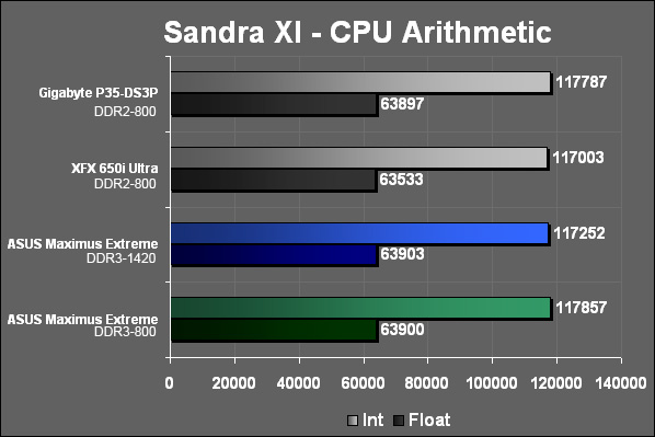
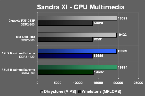
In the synthetic benchmark we can see that the DDR3 memory does not have any impact on the scores. Even with the higher latencies the DDR3 memory at its slowest speed of 800 MHz doesn’t hold back the test scores here.
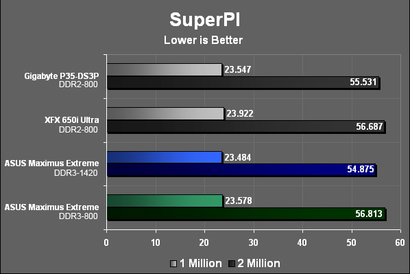
The Maximus is able to keep pace every step of the way and here we see the first signs of the performance DDR3 can offer. While not a large difference by any means, it is to be remembered that the CPU is working at the same speed and only the RAM and FSB are working faster here.
TEST RESULTS: RAM
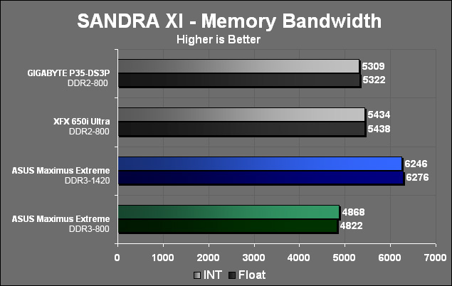
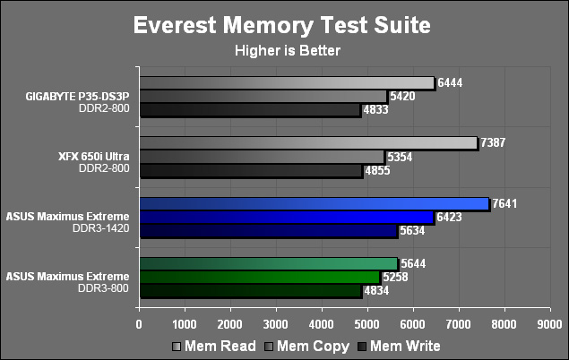
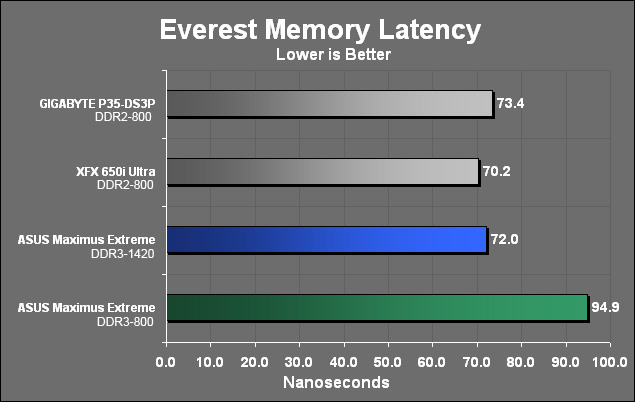
At 800 MHz we see how much the higher latencies of DDR3 affect its performance. But DDR3 is not meant to be run at such a slow speed. At 1420 MHz we start seeing what DDR3 has to offer. Don’t forget that we are also using memory that is rated for 1600 MHz which means it has even more performance left. The reason we did not run it at that speed was because it would cause our CPU to run at a faster 2.4 GHz thereby skewing the results.
TEST RESULTS: GPU
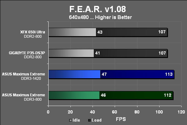
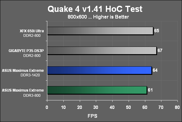
Scores for the GPU are right where they should be. We are not testing the performance of the video card here but rather how fast the CPU and RAM can pass data along to the GPU for processing. We have purposely made the CPU the bottleneck here. In F.E.A.R. we see that the board is more efficient than the other two boards at this resolution. The important piece of the puzzle that won’t materialize for some time is the impact PCIe 2.0 will have. Once more and more games begin to reach the bandwidth limit of PCIe 1.1 x16 you will be thankful you have a PCIe 2.0 board to keep you running at high frame rates.
TEST RESULTS: HDD
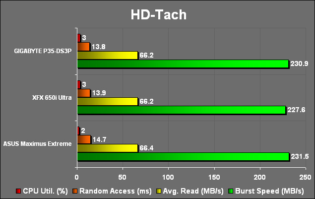
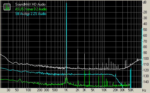
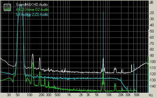
TEST RESULTS
Testing chain: External loopback (line-out – line-in)
Sampling mode: 24-bit, 192 kHz
Summary
| Test | SoundMAX HD Audio | ASUS Xonar D2 | SB Audigy 2 ZS |
| Frequency response (from 40 Hz to 15 kHz), dB: | +0.04, -0.17 | +0.06, -0.03 | +0.00, -0.00 |
| Noise level, dB (A): | -86.9 | -116.9 | -96.5 |
| Dynamic range, dB (A): | 86.5 | 116.6 | 96.1 |
| THD, %: | 0.012 | 0.0009 | 0.0004 |
| IMD + Noise, %: | 0.018 | 0.0022 | 0.0041 |
| Stereo crosstalk, dB: | -75.4 | -95.6 | -96.4 |
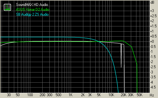
Frequency response
A measure of what frequencies can be reproduced and how accurately they are reproduced. A measurement of 20 to 20,000 Hz ± 3dB means those frequencies between 20 and 20,000 Hz can be reproduced no more than 3 dB above or below a reference frequency level.
Noise level
An unwanted portion of a signal such as hiss, hum, whine, static, or buzzing.
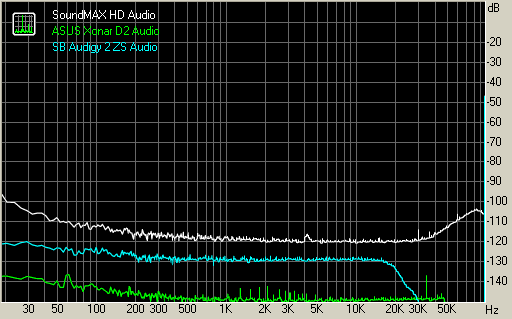
Dynamic range
Dynamic Range is a measure of a sound card’s ability to handle loud and soft sounds. It is simply the ratio of the loudest undistorted signal that the card can handle to its internal noise.
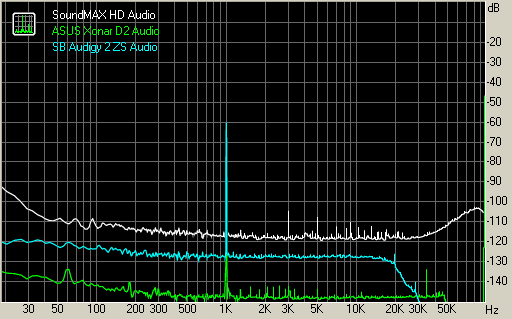
THD + Noise (at -3 dB FS)
Total Harmonic Distortion (THD) is a means for measuring Nonlinear Distortion . Nonlinear Distortion is a form of signal processing error that creates signals at frequencies that are not necessarily present in the input.
Intermodulation distortion
Intermodulation Distortion is a means for measuring Nonlinear Distortion . Nonlinear Distortion is a form of signal processing error that creates signals at frequencies that are not necessarily present in the input.
Stereo crosstalk
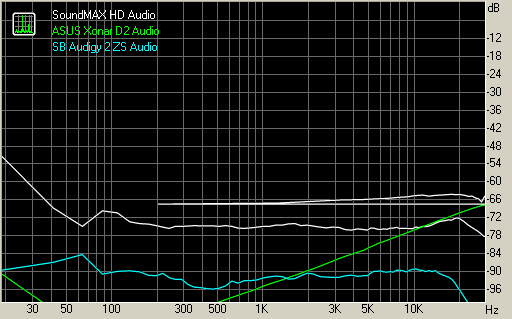
I was amazed to see just how well the “on-board” audio of this board performed. While it may not have placed first in any of the tests performed here, it was up against two very good audio cards. This is the first on board audio that I would recommend using unless you are a true audiophile who needs absolute clarity.
CONCLUSION
The Asus Maximus Extreme is one board which rewards you for your time and effort. If you like to endlessly tweak and fiddle with settings then you will have a field day with this board. Remember though that if you are new to overclocking than you will want to proceed with caution as the BIOS offers enough voltage to fry the board immediately. But Asus has a solution for those of you that are new as well and it comes in the form of the “CPU Level UP” setting. With the flick of a BIOS setting the board will adjust the necessary parameters to have your CPU run at the faster speeds of the processors listed. Assuming, of course, that the CPU can handle it. Turning to the audio portion of the board, I have used the on-board sound for the entire time I have spent with the Maximus Extreme and I really like it. Even though it may not have performed as well as the discrete sound cards I haven’t heard any noticeable difference in sound quality.
The video setup on this board is a bit convoluted though this will only affect a small portion of you. For those who plan on running this board with two cards in Crossfire mode than you will be treated with more bandwidth than you can shake a stick at. Lastly, we come to the memory portion. DDR3 is expensive right now but history tells us this won’t last forever. Also, if you prefer this board with DDR2 memory Asus has you covered with the Maximus Formula. So I won’t fault this board at all for the DDR3 memory because this is for people who need the cutting edge tech and as shown in the benchmarks DDR3 will have a lot to offer.
In the beginning of this review I posed the question, ” Is it practical?”. We each much come to our own conclusion. For me I think it is very practical. I would rather spend a bit more now on one very good board than to buy a lesser one and have to upgrade six months to a year later. But again, we each have our limits and in the immortal words Matthew Broderick from Ferris Bueller’s Day Off, “If you have the means, I highly recommend picking one up.”
FINAL WORDS
Performance: 8.5/10 – This board offers a great level of overclocking no matter how new you may be at it. Memory performance is generally good and video performance is strong.
Bundle: 10.0/10 – Asus gives you a cable for every component this board supports. You have six SATA ports, Asus hands you six cables. Nice. Throw in a free game, a ton more cables and you have the most complete bundle you can ask for.
Value: 7.0/10 – This is one expensive board and for that it is hard to give it a high value rating. Where it does very well is to give you tons of future compatibility. PCIe 2.0 and DDR3 will keep you happy for quite some time as long as you can swallow the initial cost.
Pros:
+ Highly overclockable
+ Supports newest Intel CPU’s
+ Supports new 1333 & 1600 MHz FSB
+ On board audio performs very well
+ On board power/reset/clear CMOS switches
+ PCIe 2.0
+ Supports new Penryn chips
Cons:
– Expensive
– Large CPU heat sinks may not fit
– Using third PCIe slot lowers the second one to x8 PCIe 1.1
Final score: 8.5 out of 10 and receives the Bjorn3D Seal of Approval.