Looking for an enthusiast gaming and overclocking board? Look no further than the GIGABYTE X58A-UD7 motherboard. With latest technologies including SATA 3 and USB 3.0, and high quality components, it is definitely one of the top motherboards on the market.
Introduction – Gigabyte X58A-uD7
As one of the world’s leading motherboard producers, GIGABYTE’s main focus in the motherboard industry is staying up to date with the latest technologies and using the highest quality components in manufacturing. They have consistently shown that they are capable of this, being the first to support USB 3.0 and SATA 3, and providing 3x more power to their motherboards’ USB ports. They have expanded these features to be built into their latest mainstream Intel and AMD motherboards, ensuring that these features are available to even those who cannot or do not purchase high-performance motherboards. Notwithstanding these improvements, GIGABYTE’s price tage for the X58A-UD7, a whopping $340, raises some eyebrows.
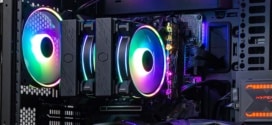
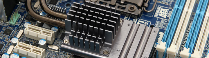
Considering that the UD7 is one of the top model motherboards in the Intel platform socket LGA1366, it makes sense for it to be priced at around $340. It is not the overall price that causes concern, but the price disparity between the UD7 and its predecessor, the UD5. The UD5, with an MSRP of $290, also comes with 16 Phase Power, 2x Gigabit LAN, and Unlocked Power features. The only big difference between the two is the cooling solution used in the UD7. The UD7 comes with the Silent-Pipe 2 cooling solution, which we will examine closely in the following pages. It includes not only an extra heatpipe cooler that attaches to North Bridge heatsink, but also an extra water cooling block that can replace the stock heatsink. Similarly, the UD3R, which is about $210, uses 12 Phase Power, no full heatpipe cooling solution, 1X Gigabit LAN, and no Unlocked Power features. From these differences in price, we can infer that the UD7 is specifically designed for gamers and overclocking enthusiasts, the UD5 is one step lower, and the UD3R provides plenty of performance for avid gamers but perhaps a bit less on the overclocking side.

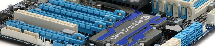
As we previously mentioned, the UD7 supports USB 3.0, SATA 3, provides 3x more power to the USB ports, and is also compatible with Multi-Display support with 3-Way SLI and CrossFireX configuration. It uses 16 Phase power for optimal cool and stable operation, and is compatible with unlocked processors for the ultimate overclocking experience. The Ultra Durable 3 motherboard design is GIGABYTE’s specialty, using 2x more copper in the PCB for less impedance, lower temperatures, better power efficiency, lower EMI, better overclocking, and better ESD protection. The Ultra Durable 3 design also includes high quality Japanese capacitors, Lower RDS(on) MOSFETs and Ferrite Core Chokes. Finally, the Rev 2.0 UD7 is fully compatible with the new Intel 6 Core 32nm Gulftown processors, and comes with ON/OFF Charge feature for easily charging removable devices like iPods. It also has LEDs that show temperatures, voltages, and other information on the motherboard for overclockers.
| Product Name | Price |
| GIGABYTE GA-X58A-UD7 | $339.99 |
| GIGABYTE GA-X58A-UD5 | $279.99 |
| GIGABYTE GA-X58A-UD3R | $209.99 |
| ASUS Rampage III Extreme | $377.41 |
| ASUS Maxiumus III Formula | $224.01 |
| ASUS P6T | $204.35 |
Features
Due to the high amount of special features included in the UD7, we will only include those that stand out from the rest. For more information and a full list of the X58A-UD7’s features, please visit GIGABYTE’s Website HERE.
- Supports new generation Intel 32nm 6 core processors
- The best CPU VRM Power design for extreme 6 core CPU overclocking
- Ultra Durable 3 Technology with copper cooled quality for lower working temperature
- Supports newest NEC SuperSpeed USB 3.0 with superfast transfer rates of up to 5 Gbps
- 3X USB power delivery for greater compatibility and extra power for USB devices
- Provides newest Marvell SE9128 high speed SATA3 storage interface with superfast 6Gbps link speed
- Supports the newest Intel Core i 7 processors in socket LGA1366 with QPI 6.4 GT/s
- Revolution energy saving design with DES 2 featuring hardware based Dynamic 6-Gear switching
- Supports 3 channel DDR3 2100+ memory
- Scalable ability to both 3 way CrossFireX and 3 way SLI support for ultimate graphics performance
- Smart 16 power phase design with mutual back-up to each 8 phase
- New Hybrid Silent-Pipe 2 design provides unequalled heat conductivity
- Unique hardware control IC to provide more precision voltage control
- 100% 50,000 hour lifespan Japanese solid capacitors design
- Onboard Debug LED display simplifies motherboard troubleshooting
- Patented DualBIOS with dual hardware BIOS protection
- 2 Gigabit Ethernet LAN with Teaming functionality
- Supports Dolby Home Theater audio to create a stunning surround sound listening experience
- Power/reset/Clr CMOS onboard button for easy operation on the workbench
- Blu-ray playback outputs supported by high quality 108dB SNR ALC889 HD audio
- Compatible with Window 7 to deliver the best operation experience
- Meet European Union ErP(Energy-related Products) requirement
Features Explained
|
Features new and improved Unlocked Power CPU VRM
 Based on Intel’s highest end X58 chipset, the GIGABYTE GA-X58A-UD7 offers a wide range of premium features tailor-made for PC enthusiasts who believe more is never enough. The latest monster performance GA-X58A-UD7 motherboard, featuring a revolutionary new 16 phase Unlocked Power design, 3-way graphics support including Nvidia SLI™ and ATI CrossFireX™, as well as a host of unique GIGABYTE features including 333 Onboard Acceleration and On/Off Charge. GIGABYTE GA-X58A-UD7 motherboards also leverage the success of GIGABYTE’s uniquely developed technologies including the GIGABYTE Ultra Durable™ 3 design, which features 2x the amount of copper of a traditional PCB design, as well as the innovative Smart6™ PC management tools, On/Off Charge for quick anytime iphone charging, Dynamic Energy Saver™ 2 power saving utilities, and DualBIOS™ technologies. |
|
 Get Ready to Unleash the Power of 32nm 6 Core CPUs
GIGABYTE’s entire line of X58-based motherboards are ready to support the new generation of Intel 32nm 6-core processors, delivering the very best platform for multitasking, multimedia and high performance gaming.
|
|
|
Dual Power Switching
The industry’s first Dual Power Switching design for delivering better durability and longer component lifespan. When Dual Power Switching is activated, 2 sets of 8 power phases operate in tandem, automatically turning on one set of 8 phases and powering down the other 8, allowing the non active set to rest. Dual Power Switching ensures that each set of phases share the power workload, effectively doubling the lifespan of the phases.
|
|
|
|
 On/Off Charge Support
GIGABYTE On/Off Charge technology that enables faster iPhone, iPad and iPod Touch charging. A derivative of GIGABYTE’s highly acclaimed 3x USB Power feature, On/Off Charge technology allows iPhone, iPad and iPod touch devices to draw more current from GIGABYTE motherboard USB ports than standard USB ports allow, with the added benefit that the PC can be on, in standby mode or even off…more |
|
 Visible Overvoltage Reminder
Debug LEDEmbedded post code LED display simplifies motherboard signals and indicates system status
|
|
 USB 3.0 Support
The GIGABYTE X58A series motherboards support the latest generation SuperSpeed USB 3.0 technology made possible through an onboard NEC uPD720200 host controller. With superfast transfer rates of up to 5 Gbps, users are able to experience an almost a 10x improvement over USB 2.0. Additionally, backwards compatibility with USB 2.0 assures users of long term use of their legacy USB 2.0 devices. The onboard NEC SuperSpeed USB 3.0 technology also provides new power management features that include increased maximum bus power and device current draw to better accommodate power-hungry devices.
|
|
 SATA 6 Gbps Support
Yet another onboard feature of GIGABYTE X58A motherboards are Marvell’s new SE9128 chips for high-speed SATA Revision 3.0 compatibility, delivering superfast 6Gbps link speeds for twice the data transfer rates of SATA Revision 2.0 (3 Gbps). When used in RAID 0 (Stripe) mode, GIGABYTE X58A series motherboards offer even faster data transfer rates of up to 4x the speed of current SATA interfaces.
|
|
 3x USB Power Boost
GIGABYTE motherboards feature a 3x USB power boost, delivering greater compatibility and extra power for USB devices. GIGABYTE’s unique USB power design is also able to efficiently regulate output over the full voltage range, which greatly enhances USB device compatibility. In addition, dedicated lower resistance fuses ensure lower voltage drops, and provide more stable and plentiful power delivery.
 |
|
 OV-Alert LED
4 sets of OV-Alert LEDs indicate the overvoltage level of the CPU, Memory, North Bridge and South Bridge to prevent component damage.
|
|
 Visible Overclocking Reminder
OC-Alert LED indicates the level of CPU overclock from low to high.
|
|
 Visible Temperature Reminder
Two sets of Temperature Alert LEDs indicate the current temperature level of the CPU and North Bridge
|
|
|
DualBIOS™ – Patented Dual Hardware BIOS Protection
DualBIOS™ is a GIGABYTE patented technology that automatically recovers BIOS data when main BIOS has crashed or failed. Featuring 2 physical BIOS ROMs integrated onboard, GIGABYTE DualBIOS™ allows quick and seamless recovery from BIOS damage or failure due to viruses or improper BIOS updating.
|
|
-Accelerating hard drive performance with ease") XHD (eXtreme HardDrive)-Accelerating hard drive performance with ease
Accelerating system performance is made easy with the user friendly GIGABYTE eXtreme Hard Drive (X.H.D). GIGABYTE eXtreme Hard Drive (X.H.D) provides a quick and easy way to boost your hard drive performance simply by adding another hard drive.
|
|
|
Multi-display support with 3 way CrossFireX and 3 way SLI™
Flexible graphics capabilities – Up to 3 VGA cards are supported for either 3 way CrossFireX™ or 3 way SLI™ action, delivering the ultimate in graphics performance for gaming enthusiasts who demand the highest frame rates without compromising on resolution.
 |
|
 GIGABYTE Ultra Durable 3 design, featuring 2 ounces of copper for both the Power and Ground layers which dramatically lowers system temperature by delivering a more efficient spreading of heat from critical areas of the motherboard such as the CPU power zone throughout the entire PCB. GIGABYTE’s Ultra Durable 3 also lowers the PCB impedance by 50%, which helps to reduce electrical waste and further lowers component temperatures. A 2oz Copper layer design also provides improved signal quality and lower EMI (Electromagnetic Interference), providing better system stability and allowing for greater margins for overclocking…more |
|
 Benefits of 2 oz Copper PCB
• Cooler than traditional motherboards
• Enhanced durability • Improved energy efficiency • Greater margins for overclocking…more |
|
|
2X Lower Impedance

In addition, doubling the amount of copper lowers the PCB impedance by 50%. Impedance is a measure of how much the circuit impedes the flow of current. The less the flow of current is impeded, the less amount of energy is wasted. For GIGABYTE Ultra Durable 3 motherboards, this means total PCB electrical waste is reduced by 50%, which also means less heat is generated. 2 ounces of copper also provides improved signal quality, providing better system stability and allowing for greater margins for overclocking. |
|
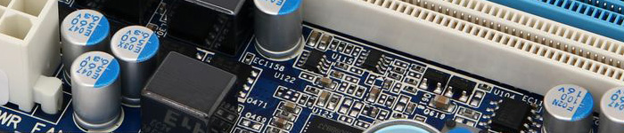
 50,000 Hours Japanese Solid Capacitors
GIGABYTE Ultra Durable motherboards are equipped with solid capacitors developed by leading Japanese manufacturers. With an average lifespan of 50,000 hours, these solid capacitors provide the stability, reliability and longevity essential to meet the power needs of high-end processors and other components running today’s most demanding applications and games…more
|
|
 Hardware OverVoltage Control IC – Enabling Extreme Overclocking
GIGABYTE Hardware Overvoltage Control ICs featuring more voltage control options than before for the CPU North Bridge and memory. The overvoltage controllers also provide hardware linear real-time voltage control, which means there is no delay compared to the GPIO controller in past implementations. In addition, GIGABYTE’s Hardware Overvoltage Controller ICs also allow for much finer voltage control, allowing power users to adjust voltage in as little increments as 20mV for better overclocking performance.
|
|
|
Onboard Quick Switches
Onboard Power, Clear CMOS and Reset buttons allow for quick and easy tweaking for power users working in an in chassis environment.
|
|
|
Qualified for Windows® 7
The motherboard qualified for WHQL (Windows Hardware Quality Labs) certification of Windows 7 from Microsoft®, setting the standard for future Windows 7 certified motherboards…more
|
|
 ErP Lot 6 support
The ErP (as known as Energy-Related Products Directive) is part of new European Union’s environment regulations. ErP established is based on the concern of environmental issues regards electronic devices been gained popularity and how to improve energy efficiency for better and greener life. GIGABYTE presents standard motherboards to help you effectively improving system performance and saving more energy.
|


Specifications
According to GIGABYTE, the UD7 is compatible with DDR3 2200MHz memory modules. We will test that statement, but our main benchmarking setup will use 1600MHz memory modules. To test the 2200MHz memory speeds, we are going to be using slightly slower Kingston 2133MHz DDR3 4GB KHX2133C9AD3W1K2/4GX modules.
Unfortunately, the UD7 only uses a standard onboard audio bus. The $340 price tag would be more appreciable if GIGABYTE would include a dedicated audio card for those who want crisper sounds and high performance. Finally, it would have been better for GIGABYTE to include a connector where users could plug in all the case cables, such as the Power Switch, Reset Switch, and LED connectors, and then use that larger connector to simply connect one collection of cables to the motherboard.
| CPU |
|
| QPI |
|
| Chipset |
|
| Memory |
(Go to GIGABYTE’s website for the latest memory support list.) |
| Audio |
|
| LAN |
|
| Expansion Slots |
|
| Multi-Graphics Technology |
|
| Storage Interface | South Bridge:
Marvell 9128 chip:
GIGABYTE SATA2 chip:
JMicron JMB362 chip:
iTE IT8720 chip:
|
| USB | Integrated in the South Bridge
NEC chip:
|
| IEEE 1394 |
|
| Internal I/O Connectors |
|
| Back Panel Connectors |
|
| I/O Controller |
|
| H/W Monitoring |
|
| BIOS |
|
| Unique Features |
|
| Bundle Software |
|
| Operating System |
|
| Form Factor |
|
| Note | (Note 1) Due to Windows Vista/XP 32-bit operating system limitation, when more than 4 GB of physical memory is installed, the actual memory size displayed will be less than 4 GB. (Note 2) For optimum performance, if only one PCI Express graphics card is to be installed, be sure to install it in the PCIEX16_1 slot; if you are installing two PCI Express graphics cards, it is recommended that you install them in the PCIEX16_1 and PCIEX16_2 slots. (Note 3) The PCIEX8_1 and PCIEX8_2 slots share bandwidth with the PCIEX16_1 and PCIEX16_2 slots espectively. When PCIEX8_1 is populated with an expansion card, the PCIEX16_1 slot will operate at up to x8 mode; when PCIEX8_2 is populated with an expansion card, the PC IEX16_2 slot will operate at up to x8 mode. (Note 4) Whether the CPU/system fan speed control function is supported will depend on the CPU/ system cooler you install. (Note 5) Available functions in EasyTune may differ by motherboard model. |
| Remark |
|
Software and Features Quick Overview

Here are some great applications that GIGABYTE includes with the UD7 motherboard. Most of these applications also come with other model motherboards, including the Intel platform X58, P55, H57, H55, P45, P43 G41 series motherboards, and AMD 800 and 700 series motherboards. For more information about certain features, please make sure to check on GIGABYTE’s website to see if the motherboard supports those features.
The descriptions provided by GIGABYTE do an excellent job explaining what each of the applications do. In the interests of thoroughness, however, we note that the Dynamic Energy Saver 2 feature would freeze our system every single time we enabled it. Under stock settings, when the computer is stable, the Dynamic Energy Saver 2 worked very well. It comes with a very nice counter that shows exactly by how many kilowatts the application has reduced the computer’s energy waste.
 Dynamic Energy Saver™ 2
GIGABYTE Dynamic Energy Saver™ 2 incorporates a host of intelligent features that use a proprietary hardware and software design to considerably enhance PC system energy efficiency, Reduce power consumption and deliver optimized auto-phase-switching for the CPU, Memory, Chipset, VGA, HDD, and fans with a simple click of button.
|
||||||||||||
 Cloud OC
GIGABYTE Cloud OC is a free overclocking application that facilitates PC overclocking through any web browsing capable device such as a smart phone, iPad, iPhone, Netbooks or notebook PC. Being browser based it connects via wireless Internet, Bluetooth or through an Ethernet cable and its many functions are categorized into three tabs: Tuner, System Info and Control…more |
||||||||||||
 Hotkey OC
GIGABYTE Hotkey OC allows users to create and save various profiles that can be adopted for different benchmarks. Hotkey OC then allows users to jump between these profiles on the fly so that the best profile for each segment within the benchmark can be used to optimize scores and boost overall performance. So, for example, when running 3DMark 06 the 1st profile might be optimized for graphics and can be used for the first two graphics tests, then the next two tests can utilize the 2nd profile which might be optimized for CPU tests, and one could jump back to the 1st profile again for the final two graphics (shader) tests…more |
||||||||||||
|
Smart 6- A Smarter way for PC system Management
GIGABYTE Smart 6™ is designed with user-friendliness in mind, and offers a combination of 6 innovative software utilities that provide easier and smarter PC system management. Smart 6™ allows you to speed up system performance, reduce boot-up time, manage a secure platform and recover previous system settings easily with a click of the mouse button.
|
||||||||||||
 AutoGreen- Greening your PC via Bluetooth cellphone
AutoGreen technology can automatically save power for you simply by your bluetooth cell phone when you are away from your computer.
Note: GIGABYTE motherboards do not include a Bluetooth® receiver; the addition of a 3rd party Bluetooth receiver is required. |
||||||||||||
 EasyTune6
GIGABYTE has completely redesigned EasyTune6 from the ground up to make it easier than ever to manage and monitor your hardware resources as well as tweak your system settings in order to achieve maximum system performance. Whether you are an overclocking enthusiast, or a computer novice, EasyTune6 provides the tools you need to quickly and effortlessly fine tune your system.
|


Checking out the X58A-UD7


Finally, here are all the accessories that were included in the accessory box:
- IDE Cable
- Floppy Cable
- 4 SATA Cables
- 2-port eSATA PCI Expansion Bracket (with accompanying eSATA cables)
- 2-Way SLI bridge connector
- 3-Way SLI bridge connector
- I/O Panel
The Motherboard from all angles


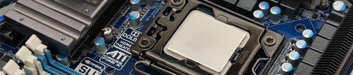
Finally, from the picture which shows the front of the motherboard, we can see that there are a total of 4 system fan connectors, two of which are PWM fan connectors. There is also one more fan connector right next to the North Bridge cooler.


On the second picture we can see one of the system 3-pin fan headers on the far left side. Right next to it to the right, we see the 24-pin power connector and 3 phase power for the memory slots. These help make sure that the voltages on the memory modules are as stable as possible. The memory slots are quite close to the CPU socket though, those who wish to install CPU coolers like the Thermalright TRUE Black 120 or the Noctua NH-U12P should be aware that tall memory modules will not fit. It is possible to turn the CPU cooler around by 90 degrees, but some tower CPU coolers will not fit that way either due to the North Bridge cooler. Lastly, we see a power switch, a reset switch and several LEDs right next to the Power switch to show how high the BCLK is raised in the BIOS. The more LEDs that light up, the higher the BCLK is set to.


The back left side of the motherboard has all connectors that will be visible on the back of the case: the PS/2 Keyboard and Mouse Ports, the Optical S/PDIF Out connector that provides digital audio out to an external audio system that supports digital optical audio. Below the Optical S/PDIF, GIGABYTE also included a Coaxial S/PDIF Out Connector which is essentially an Optical S/PDIF except for Coaxial audio devices. Following, we have a very handy “Clear CMOS” button, which allows us to clear the CMOS in case overclocking goes into unstable areas and the system will not boot. Then we have two firewire IEEE 1394a ports, two USB 2.0/1.1 ports, and two eSATA/USB combo connectors. It is very interesting that we see the support for both either USB or eSATA. This saves space and users can use the connectors for USB when eSATA is not being used. Subsequently, we also have two more USB 2.0/1.1 ports, two RJ-45 LAN ports that are capable of up to 1Gbps data rate, two USB 3.0 ports that are 10x faster than the previous USB 2.0 ports, and standard audio input and output jacks. We would also like to add that it would have been nice to have a dedicated sound card instead of an onboard audio codec due to the fact that this motherboard is more expensive than the UD5 with only minor changes. After testing the audio output power of the onboard audio connector, we found that an old Dell Inspiron e1405 laptop could produce the same amount of volume at 20% setting as the UD7’s onboard bus could at 100%. The audio performance is insignificant with large speakers that use external power adapters, but for large headphones that require more power, it could be a problem.


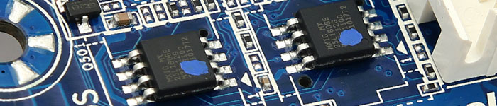
On the same pictures, we can also see the iTE IT8720F chip, which is responsible for the floppy connector and the PS/2 Keyboard and Mouse connectors. A bit higher up by the F_AUDIO connector, there are two Realtek RTL8111E chips that take care of the two 1Gbit LAN connectors. In between the Realtek and iTE chips, there is one more chip which is responsible for the audio codec used on this motherboard. Then on the second picture, the two BIOS chips are clearly visible. In case one BIOS chip gets damaged, the second one takes over. Lastly, we can also see the Floppy connector and two more fan connectors. One of them is a 3-pin fan header while the other one is a 4-pin PWM fan header.


The second picture reveals the pins for the Socket LGA 1366. We can see that GIGABYTE also decided to use Japanese Solid Capacitors, which run cooler and work for longer than the older capacitors.


BIOS
(Picture of GIGABYTE’s Dual BIOS)


Lastly, the PC Health Status section shows all important information about fan speeds, temperatures, voltages, and gives extra options for temperature and fan settings. The last picture is the Intel Matrix Storage Manager which enables users to set up hard drives in a RAID 0/1/5/10 configurations. In this picture a RAID 0 configuration is already set up with two Western Digital RAID Edition 3 hard drives.
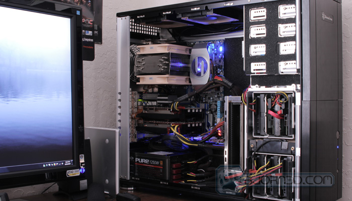
First Boot – Intel Core i7 920 C0
After setting up the UD7 in a Silverstone Temjin TJ10 chassis and loading the necessary hardware, including a Core i7 920 C0 revision CPU, OCZ 6x2GB 12GB DDR3-12800 1600MHz memory modules, and two new Palit GTX460 Sonic Platinum video cards in SLI, we booted up the system. We noticed right away that the memory modules were recognized and were automatically set to run at 1066MHz. Examination of the BIOS showed that the System Memory Multiplier was set to 8x (that’s 8 x 133 = 1064MHz). We increased the multiplier to 12x, so the memory modules would run at the stock 1600Mhz frequency. We also made sure the DRAM Voltage was set to 1.64V and timings were set to stock settings at 8-8-8-24 2T. When we restarted the system, we got a blank screen. After careful investigation, we realized that when our last motherboard had fried, it had also damaged the CPU. We tried loosening the timings a bit to 9-9-9-30, but the system still did not boot at 1.65V. After receiving a new Core i7 930 in the mail, we installed it right away, and the system successfully booted up at 1600MHz at the correct timings and voltage. We also switched out the OCZ memory modules to a Kingston 2133MHz DDR3 Dual-Channel 4GB kit to see how the motherboard would react to those modules. The memory was recognized, but only at 1066Mhz, and after tweaking the BIOS we easily booted at 2000Mhz. However, reaching 2133MHz with the Core i7 930 was still difficult. It is important to understand that most of the time the limitation is not in the motherboard, but in the memory controller on the CPU. It takes a very powerful CPU (Extreme, Unlocked) to achieve stability at 2133MHz on such motherboards.

Overclocking with the UD7 – Core i7 920 C0
When the first booting problem started with the OCZ memory, we wondered how the system would handle overclocking, but it ended up being a very enjoyable process. On the old ASUS P6T motherboard, when we set the BCLK to 180 and the CPU Clock Ratio to 20x, we still had to adjust voltages for a stable boot. Since GIGABYTE is well known both for overclocking to high clock speeds and for setting world records, we wondered how well it would run if we kept all the voltages at AUTO. This also puts GIGABYTE’s Ultra Durable 3 motherboard design to the test, because they state that their motherboards are more stable than traditional motherboards due to the double copper layer they use in their PCB. We saved the settings and restarted the system after setting the BCLK to 180 and CPU Clock Ratio to 20x. There was no problem with booting and the voltages were automatically set. Now we were running 3.6Ghz at 1.38V, and when Windows 7 booted up, we ran LinX for several hours to confirm that everything was stable. There were no errors, but the core temperatures on the processor were hitting 91C, along with the motherboard at 60C.
We would like to mention that we are running a quiet system with lower air circulation than an average overclocked gaming system. The case does not come with any side ventilation, only one 120mm front intake fan, and two 120mm outtake fans on the top and one 120mm outtake fan on the back. We also have installed the Thermaltake TRUE Black 120 CPU cooler and two Noctua NF-P12 120mm quiet fans. Also, this Core i7 920 is a C0 revision which tends to run hotter then the newer D0 revision due to higher voltages required for overclocks.
We were still not satisfied with the overclocked processor and the temperatures we were getting. We started overclocking manually by first finding the maximum BCLK that the motherboard could run at. To do that, we set the CPU multiplier to 12x so as not to stress the processor too much. We also found the lowest voltages that were stable: 0.9V on the 920 C0. After slowly raising the BCLK and the CPU, QPI, VTT, and NB voltages, we finally found the limit at 213MHz (the system would not boot at 214MHz even when the motherboard voltages were raised into the red zones). We ensured plenty of air circulation through the system by using a large house fan to blow air into the computer. This limited the risk of component blowouts due to overvolting.
When we found the maximum BCLK on the UD7, we lowered it to 200MHz to make relieve stress on the motherboard. We then gradually increased the multiplier from 12x to 18x. We were curious to see whether we could reach the same 3.6GHz speeds without having to use 1.38V for the VCore. As we believed, this worked, and we achieved 3.6GHZ stably at 1.2875V in the BIOS (CPU-Z showed this as 1.248V). That is impressive, because we could not get the Core i7 920 stable at 1.2875V on the ASUS P6T motherboard. The lowest we could go on that motherboard was around 1.35V in CPU-Z. That’s a 0.1V difference between the two motherboards.

We were very impressed with GIGABYTE’s overclocking performance when it came to the processor. Interestingly, the memory on the motherboard would not run at higher speeds than 1440MHz when the processor was overclocked (Damaged Memory Controller on the Core i7 920 C0). As an 8x multiplier on the motherboard started hitting high speeds on the memory, we were forced to reduce the multiplier to 6x to keep the memory stable at 1200MHz. So that’s 6×200=1200MHz. I could however lower the timings to 7-7-7-18. The temperatures on the processor were a lot better. With at lower voltage required to run the processor in stable condition, the temperatures dropped to 80C max on Core 0. This is about a 10-12C difference from the AUTO settings that the GIGABYTE board set the voltages to when the processor was running at 20 x 180MHz.
We continued pushing the motherboard and processor further. The next overclock that we managed was at 3.74GHz. We will use this to benchmark this motherboard against the ASUS Maximus 3 motherboard with a Core i5 processor overclocked to 3.74GHz. To make things more accurate, because our Core i7 920 C0 revision cannot run at speeds higher than 1440MHz, we will be using our new Core i7 930 D0 revision CPU to clock the memory at close to 1600Mhz and 3.74GHz on the processor. The processor required 1.35V at 3.74GHz, and the voltages seemed to jump up quite high from there on. We pushed it even further and was able to achieve 4.2GHZ at 1.424V according to CPU-Z and 4.3GHz at 1.536-1.520V.


We were once again very impressed because we could not get through the 4.2GHz barrier with the ASUS P6T motherboard, but we could with the GA-X58A-UD7 Rev 2.0 motherboard.
Overclocking with the Core i7 930 D0
We will not go into too much detail about the Core i7 930, because we followed the same process for overclocking that we did with the Core i7 920 C0. We did however set my memory frequency to 1600Mhz with an 8x multiplier on the memory. The pictures below show several overclocked settings that were completely stable, and how we managed to get really low voltages, decent temperatures, and high clock speeds with a quiet system running on air.

In the first picture, we were looking for the lowest voltage we could use on a stock CPU. We managed to go down to 0.944V and run completely stable even after 3 hours and 15 minutes.

In this picture, we got up to 3.6GHz by setting the Base Clock (BCLK) to 200MHz and the multiplier to 18x. The voltages on the 930 D0 revision CPU were about 0.064V lower than on the Core i7 920 C0 processor. This resulted in a temperatures about 4 degrees on Core #0.

Finally, we wanted a setting for our system that we could use for everyday purposes, so we settled at around 3.8GHz, because going to 4.0GHz required an increase of 0.1V on the VCore, and our air cooling would not be sufficient to cool the CPU. At 3.8GHz, our voltages were at 1.232V, which is still lower than what we got with the Core i7 920 at 3.6GHz. This also means that our temperatures with the Core i7 930 D0 running at 3.8GHz (1600Mhz Memory) and 1.232V were about 2 degrees Celsius lower than on the Core i7 920 C0 running at 3.6GHz (1200Mhz Memory) and at 1.248V. The LinX stress test on the CPU and Memory proves that the system was still running stable after the 9 hour 27minute stress test.
Different Overclocked settings that were 100% stable:

We can see that speeds higher than 3.8GHz require a huge increase in voltage for stability. This is the point where the CPU Frequency-to-Voltage ratio starts taking the shape of an exponential graph. From this data, we can infer that increasing from 4.0GHz to 4.2GHz will need an even higher increase.
Testing & Methodology
We’ve expanded our testing suite considerably for the X58 chipset, and will continue to use the same methods for most of the motherboards and CPU’s we test. In the interests of thoroughness and accurate results, we run each test at least three times, and some tests more than that. We average the total of all the tests from each benchmark then report the average here.
The OS we use is Windows 7 Pro 64bit with all patches and updates applied. We also use the latest drivers available for the motherboard and any devices attached to the computer. We do not disable background tasks or tweak the OS or system in any way. We turn off drive indexing and daily defragging. We also turn off Prefetch and Superfetch. This is not an attempt to produce bigger benchmark numbers. Drive indexing and defragging can interfere with testing and produce confusing numbers. If a test were to be run while a drive was being indexed or defragged, and then the same test was later run when these processes were off, the two results would be contradictory and erroneous. As we cannot control when defragging and indexing occur precisely enough to guarantee that they won’t interfere with testing, we opt to disable the features entirely.
Prefetch tries to predict what users will load the next time they boot the machine by caching the relevant files and storing them for later use. We want to learn how the program runs without any of the files being cached, and we disable it so that each test run we do not have to clear pre-fetch to get accurate numbers. Lastly we disable Superfetch. Superfetch loads often-used programs into the memory. It is one of the reasons that Windows Vista occupies so much memory. Vista fills the memory in an attempt to predict what users will load. Having one test run with files cached, and another test run with the files un-cached would result in inaccurate numbers. Again, since we can’t control its timings so precisely, it we turn it off. Because these four features can potentially interfere with benchmarking, and and are out of our control, we disable them. We do not disable anything else.
Test Rig
| Test Rig | |
| Case | Silverstone Temjin TJ10 |
| CPU |
Intel Core i7 920 @ 3.74GHz Intel Core i7 870 @ 3.74GHz |
| Motherboard |
GIGABYTE X58A-UD7 Motherboard – LGA1366 ASUS P6T Motherboard – LGA1366 ASUS Maximus III Extreme – LGA1156 |
| Ram | OCZ DDR3-12800 1600Mhz (7-7-7-16 1.64v) 12GB Kit |
| CPU Cooler | Thermalright True Black 120 with 2x Noctua NF-P12 Fans |
| Hard Drives |
4x Seagate Cheetah 600GB 10K 6Gb/s Hard Drives 2x Western Digital RE3 1TB 7200RPM 3Gb/s Hard Drives |
| Optical | ASUS DVD-Burner |
| GPU |
2x Palit GTX460 Sonic Platinum 1GB GDDR5 Video Cards in SLI |
| Case Fans |
2x Noctua NF-P12 120mm Fans – Top 1x Silverstone 120mm Fan – Front and Back 1x Noctua NF-P12 120mm Fans – Hard Drive Compartment |
| Additional Cards |
LSI 3ware SATA + SAS 9750-8i 6Gb/s RAID Card |
| PSU |
Sapphire PURE 1250W Modular Power Supply |
| Mouse | Logitech G5 |
| Keyboard | Logitech G15 |
Test Suite
We will use the following applications to test the performance of the motherboard. Benchmarks
| Benchmarks |
|---|
| Excel 2007 |
| Blender |
| SiSoft SANDRA 2010 |
| Everest Ultimate Edition |
| AutoMKV |
| Cinebench R10 64-bit |
| 3DMark Vantage |
| WinRar v.3.80 |
| Pro Show Gold 4.1 |
| POVRay |
| HD Tach 3.0.4.0 |
| HDTune Pro |
| ATTO |
| Heaven Benchmark |
After the aforementioned tests, we will also dedicate a page to testing USB 3.0 benchmarks. Using several hard drive benchmarking applications, we will see how high our maximum benchmark score is with a RAID0 hard drive setup through USB 3.0. We’ll compare the results to USB 2.0 to see what the actual speed difference is between the two.
Everest Ultimate

“EVEREST Ultimate Edition is an industry leading system diagnostics and benchmarking solution for enthusiasts PC users, based on the award-winning EVEREST Technology. During system optimizations and tweaking it provides essential system and overclock information, advanced hardware monitoring and diagnostics capabilities to check the effects of the applied settings. CPU, FPU and memory benchmarks are available to measure the actual system performance and compare it to previous states or other systems. Furthermore, complete software, operating system and security information makes EVEREST Ultimate Edition a comprehensive system diagnostics tool that offers a total of 100 pages of information about your PC.”
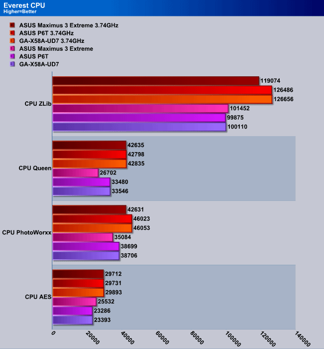
Each of these CPU test are a bit different from each other. For example while one of them performs mathematical calculations, the other might perform photo related calculations, including turning photos, resizing, etc. As many of our readers know, the ASUS Maximus 3 Extreme motherboard is actually a LGA 1156 motherboard with Dual-Channel Memory slots. The ASUS P6T and the GIGABYTE GA-X58A-UD7 motherboards are LGA 1366 and Triple-Channel motherboards. Interestingly we noticed a pattern in some of these tests. For example the CPU PhotoWorxx, while the processors were actually clocked at the same speed and had the same amount of cores and threads, the triple channel motherboards had advantage over the dual-channel motherboard in this benchmark. The performance between the P6T and the UD7 were almost identical, but the UD7 still managed to be in the #1 spot in most tests.
Everest Ultimate Memory Suite
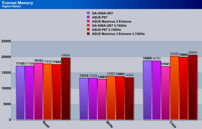
In the memory performance benchmark, the UD7 dominated the write speed test in the overclocked settings while the P6T and the Maximus 3 Extreme dominated the other tests.
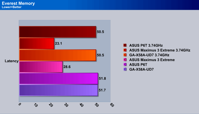
When we ran the previous memory performance tests, the UD7 did not do so good compared to the other motherboards, so we were wondering how the UD7 will perform in the latency benchmark. We see similar results here, where the UD7 was only been able to perform only by 0.1ms faster on the stock settings.
Sisoft Sandra 2010
“SiSoftware Sandra (the System Analyser, Diagnostic and Reporting Assistant) is an information & diagnostic utility. It should provide most of the information (including undocumented) you need to know about your hardware, software and other devices whether hardware or software. It works along the lines of other Windows utilities, however it tries to go beyond them and show you more of what’s really going on. Giving the user the ability to draw comparisons at both a high and low-level. You can get information about the CPU, chipset, video adapter, ports, printers, sound card, memory, network, Windows internals, AGP, PCI, PCI-X, PCIe (PCI Express), database, USB, USB2, 1394/Firewire, etc.”
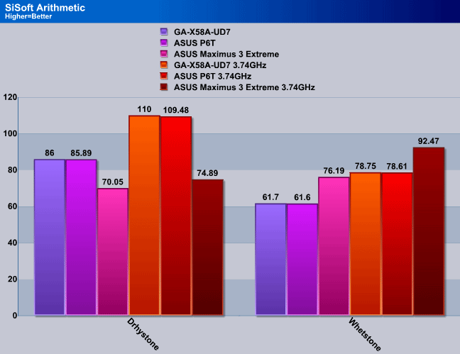
The SiSoft Sandra Arithmetic benchmark performs several different arithmetic calculations to determine performance on the CPU. In the Drhystone benchmark, the UD7 was able to pull forward in front of the other two motherboards, while in the Whetstone benchmark, the UD7 was able to beat the P6T (X58 chipsets), while it lost to the Maximus 3 Extreme (P55).
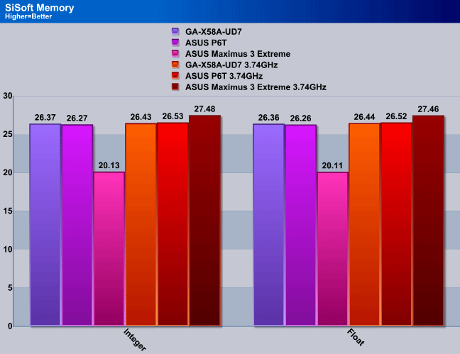
On the SiSoft Sandra Memory benchmark, we saw the same results as we have seen on the Everest memory benchmark. The UD7 fell short on the memory benchmarks compared to the other motherboards, especially when the CPUs were overclocked.
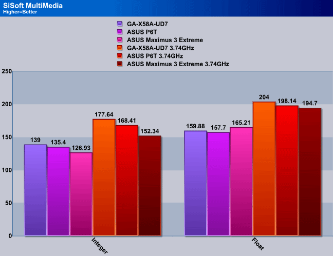
I’m quite pleased with the following results on the MultiMedia benchmark. While I work a lot with multimedia, it is good to know that the UD7 performed far better on multimedia than the other motherboards.
Cinebench R. 10.5

“CINEBENCH is a real-world test suite that assesses your computer’s performance capabilities. MAXON CINEBENCH is based on MAXON’s award-winning animation software, CINEMA 4D, which is used extensively by studios and production houses worldwide for 3D content creation. MAXON software has been used in blockbuster movies such as Spider-Man, Star Wars, The Chronicles of Narnia and many more. MAXON CINEBENCH runs several tests on your computer to measure the performance of the main processor and the graphics card under real world circumstances. The benchmark application makes use of up to 16 CPU’s or CPU cores and is available for Windows (32-bit and 64-Bit) and Macintosh (PPC and Intel-based). The resulting values among different operating systems are 100% comparable and therefore very useful with regard to purchasing decision-making. It can also be used as a marketing tool for hardware vendors or simply to compare hardware among colleagues or friends.”
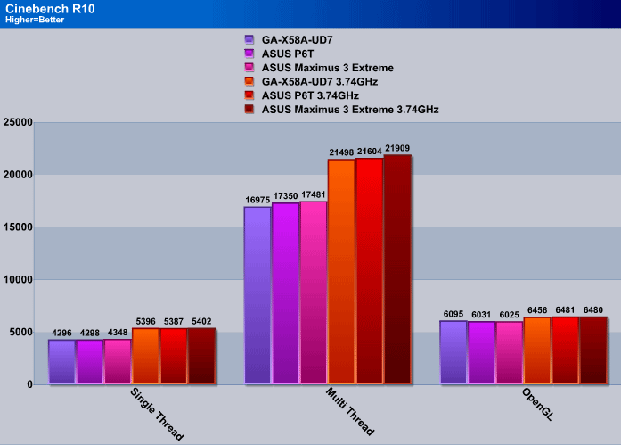
Cinebench R10, which requires multi threaded 3D rendering proved that the UD7 might just not be as scalable in multi threaded applications like Cinema 4D as the other motherboards. The ASUS Maximus 3 Extreme showed quite a bit of performance increase in the CPU speed even when the frequencies were at the same settings. This performance increase will only have about 1 second difference in 3D rendering over the UD7 and the P6T. The rendering difference would only be clearly visible if a full 3D animation would be rendered that requires several hundred frames to be rendered. After each 60 frames, you would grant at least 1 minute in rendering speed. So at 600 frames you would see a 10 minute difference between the different motherboards, and at 6000 frames, a 100 minute difference, which is 1 hour and 40 minute difference. However, rendering 6000 frames would take about 3 days to render if the scene does not change significantly, so that extra 1 hour and 40 minutes is not too much, unless you are on a strict timeframe.
POV-Ray 3.7 Beta 28

The Persistence of Vision Ray-Tracer was developed from DKBTrace 2.12 (written by David K. Buck and Aaron A. Collins) by a bunch of people (called the POV-Team) in their spare time. It is a high-quality, totally free tool for creating stunning three-dimensional graphics. It is available in official versions for Windows, Mac OS/Mac OS X and i86 Linux. The POV-Ray package includes detailed instructions on using the ray-tracer and creating scenes. Many stunning scenes are included with POV-Ray so you can start creating images immediately when you get the package. These scenes can be modified so you do not have to start from scratch. In addition to the pre-defined scenes, a large library of pre-defined shapes and materials is provided. You can include these shapes and materials in your own scenes by just including the library file name at the top of your scene file, and by using the shape or material name in your scene. Since this is free software feel free to download this version and try it out on your own.
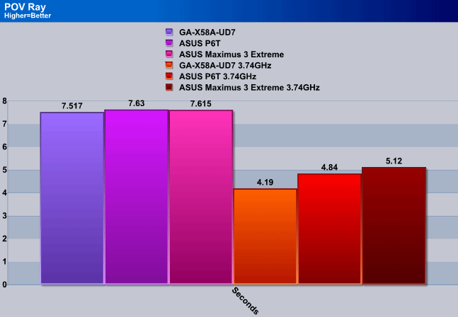
POV-Ray puts the same 3D rendering test into action as Cinebench R10 did, however, in this test, the actual rendering performance was exactly the opposite from Cinebench. The UD7 actually performed the best, and took the shortest amount of time to render the scene. We do not really have a 100% explanation why this happened.
WinRar v. 3.80

This module in WinRar generates random data, which contains specially introduced redundancy, increasing the load to both the processor and memory. Data is then passed through RAR compression and decompression algorithms, and the output of the decompression algorithm is compared to the source data. If any differences are found, WinRar then reports “Errors found – Yes” in the command window. WinRar displays a size of processed data and compression speed, current and resulting, in kilobytes per second.
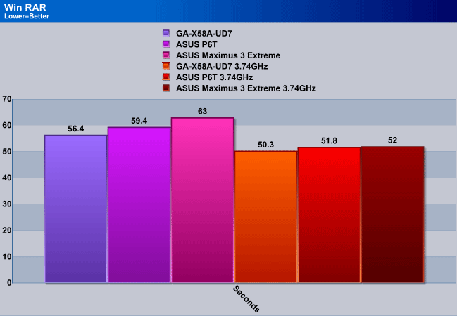
Since WinRAR also depends on the write speed of the hard drives, it is not a perfect test if different computers are tested for results, however since we are using the same hardware on each of our motherboards, we can be safe on not having skewed results. The UD7 showed a big performance increase in archiving 5 large TIFF images at stock settings over the other motherboards, but once the CPU was overclocked, the results came quite close to each other, but the UD7 still managed to outperform the P6T and the Maximus 3 Extreme.
Blender
Blender is a free open source 3D content creation suite that is available for various operating systems. The application is popular among many independent animation studios and game makers. For more information, please visit http://www.blender.org/.
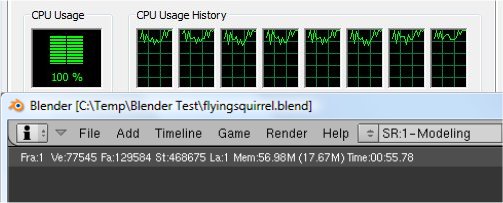
The workload consists of a ~6.9 MB character model of a flying squirrel. Due to time constraints we don’t render the entire image, as this would be time consuming and rather pointless (though the benchmark results would be larger, the ratios would stay the same). The squirrel’s right arm is large enough to show differences in CPU performance, yet small enough that we don’t have to waste 45 minutes of rendering on a single result.
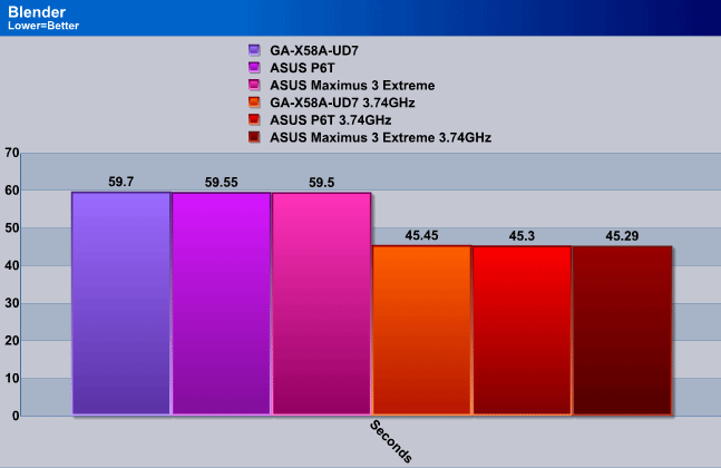
Finally, in Blender, which is yet another 3D modeling and animating application, the rendering performance was quite similar to each other. From the tiny bit of performance increase the UD7 had, the performance should not be too drastic between the different motherboards even on larger project files.
Photodex ProShow Gold 3.2

ProShow Gold allows you to combine videos and photos and music to create slide shows, depending on the end user results can be spectacular. The application allows the end user to share photos and memories with friends in a unique and spectacular way, the different formats supported are, DVD, PC and Web. Still Photos are brought to life by adding motion effects. Supported effects include, Pan, Zoom, and rotate. You can also add captions and over 280 transition effects.
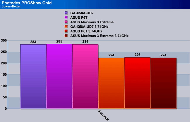
Photodex PROShow Gold is a bit different from the other rendering applications. Film editing applications usually take advantage of the memory, so memory speeds and sizes can change rendering speeds. The results were very close, and in most cases when we ran the benchmarks the results were identical to the other motherboards as well.
Microsoft Excel 2007
Monte Carlo Black-Scholes Option Pricing Test
Microsoft Excel is the widely known and most used spreadsheet application for the manipulation and calculation for number crunching. With Excel you can analyze and share information on small scale or the largest scale you can imagine. We’ve seen spreadsheets in every day use that contain literally tens of thousands of numbers and hundreds of equations. Bjorn3D uses two tests in Excel to determine CPU and Motherboard performance.

This workload calculates the European Put and Call option valuation for Black-Scholes option pricing using Monte Carlo simulation. It simulates the calculations performed when a spreadsheet with input parameters is updated and must recalculate the option valuation. In this scenario we execute approximately 300,000 iterations of Monte Carlo simulation. In addition, the workload uses Excel lookup functions to compare the put price from the model with the historical market price for 50,000 rows to understand the convergence. The input file is a 70.1 MB spreadsheet.
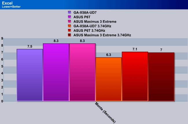
The Excel benchmark is a bit unrealistic in the sense that usually a person does not have thousands of lines of data that needs to be calculated. Even in such situation, the time difference between the motherboards is not too big which would lead to the user picking a different motherboard. We ended up sharing the results anyway. The UD7 had a clear performance boost over the other motherboards but we do not have a clear explanation why this might be the case.
3DMark Vantage

For complete information on 3DMark Vantage Please follow this Link:
www.futuremark.com/benchmarks/3dmarkvantage/features/
The newest video benchmark from the gang at Futuremark. This utility is still a synthetic benchmark, but one that more closely reflects real world gaming performance. While it is not a perfect replacement for actual game benchmarks, it has its uses. We tested our cards at the ‘Performance’ setting.
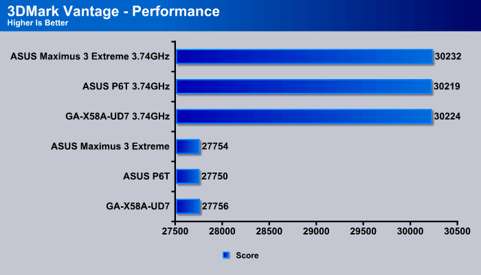
Because we did not have an GPU/CPU combination test previously, 3DMark Vantage will be a perfect application to use to benchmark the performance between the motherboards. This benchmark showed that the scalability between the GPUs running in SLI is not really any different from the other motherboards. The scores are way to close to each other, so there is actually no real winner here, because the results could wary after each run by about 1% to 2%.
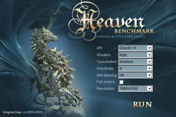
Unigine Heaven 2.1

Unigine Heaven is a benchmark program based on Unigine Corp’s latest engine, Unigine. The engine features DirectX 11, Hardware tessellation, DirectCompute, and Shader Model 5.0. All of these new technologies combined with the ability to run each card through the same exact test means this benchmark should be in our arsenal for a long time.
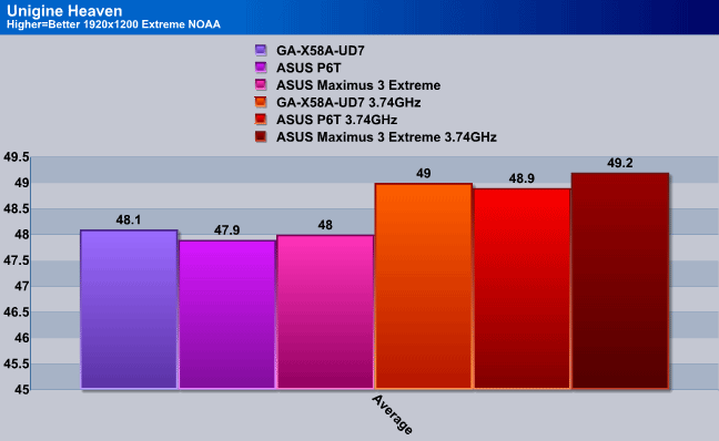
The performance difference on graphical benchmarks were minimal as well, with the UD7 performing the best in Stock settings while the Maximus 3 Extreme performing the best under Overclocked settings.
The following hard drive speed tests were tested through the USB 3.0 connectors on the GA-X58A-UD7 motherboard with the Ineo I-NA309D Pro USB 3.0 Dual-Bay RAID Enclosure. The performance on a RAID0 configuration should be enough to stress the USB 3.0 controller to see some high results.
HDTach 3.0.4.0
RAID 0

HD Tune Pro

ATTO

Crystal Disk Mark

On the following 3 different benchmarks, there is not much to explain because the USB 3.0 performance is just astonishing. We just included two other hard drive setups through our USB 3.0 Dual-Bay hard drive enclosure to give an idea on how much performance is there to expect with different enclosures at different hard drive settings.
Real Life Testing
| Copying 45 Video Files (20.2GB) | |
|---|---|
| RAID 0 |
3min 9sec |
| RAID 1 |
5min 20sec |
| Single |
3min 47sec |
| USB 2.0 Single | 12min 38sec |
This performance comparison between USB 2.0 and USB 3.0 might be the actual benchmark that our readers will want to hear about the most. The difference between a Single USB 3.0 hard drive setup and a Single USB 2.0 hard drive setup is 8min and 49 seconds. This time difference is tremendous, considering that we were only copying 20.2GBs to the external enclosure. In case we would need to copy over 500GBs of files, the time saved over backing up the files could well be 1-3 hours over USB 2.0. Because there are SSDs and other faster solutions available now for USB 3.0, the performance could even be greater than what we have shown here.
Conclusion
We were not happy to see that GIGABYTE only put 16 Phase Power on the second revision of the GA-X58A-UD7 motherboard. The older first revision had a total of 24 Phase Power, so why did GIGABYTE change this? It seems when the UD9 came out, GIGABYTE wanted to keep the UD9 at the top of the market for overclocking performance, and have the UD7 as a runner up, with a better cooler setup than the UD5. However, improving the cooler design does not justify the price difference between the UD5 and the UD7. If GIGABYTE had left at least 20 Phase Power on the UD7, the price differences between the UD5, UD7, and the UD9 would have been fair.
The actual performance of the motherboard was great. While in some tests the UD7 dominated, in others the ASUS boards came out on top. However, the performance differences are only very slight, which means that the user will most likely never notice it. The real performance lies behind the overclockability of the motherboard and how it handles CPU overclocking. We noticed that on the GIGABYTE GA-X58A-UD7 Rev 2.0 motherboard, we were able to achieve the same overclock on our Intel Core i7 920 at 0.1V lower then on our ASUS P6T motherboard. This was very impressive. The auto overclocking capability between the two motherboards was quite similar, with the difference that the UD7 actually ran stably at 3.6GHz while the ASUS P6T motherboard was not 100% stable on AUTO settings.
The temperatures on the motherboard were not very different from the temperatures that we might have seen on other motherboards. We usually see the X58 chipsets running at around 38C idle, and at around 58C load. The GIGABYTE GA-X58A-UD7 motherboard with the Hybrid Silent-Pipe 2 solution actually ran at around 58C load, sometimes hitting around 60-62C when the room temperatures went up to around 28-30C. These temperatures were recorded under overclocked CPU settings at a 200 BCLK. We did not see any improvement in cooling, even with the inclusion of the Hybrid Silent-Pipe 2 solution. However, the motherboard stayed stable, even when we pushed it to critical voltages.
Through our testing, we can conclude that if the end-user does not require 4-Way SLI or CrossfireX support but still wants to coax as much out of their system as possible, the X58A-UD7 would be the best choice for a motherboard. Its definitely a perfect motherboard for enthusiast gamers, and overclockers. For those that don’t require the extra cooling, we would like to suggest the GA-X58A-UD5 motherboard, and for people that need decent overclocking features, and still have the USB 3.0 and SATA 3.0 features, the GA-X58A-UD3R would be a perfect solution.
| OUR VERDICT: GIGABYTE GA-X58A-UD7 Rev 2.0 Motherboard | ||||||||||||||||||
|
||||||||||||||||||
| Summary: The GA-X58A-UD7 is a great motherboard that provides versatility and performance all in one package. The USB 3.0 support give it potential for the future, and the many other features such as SLI and CrossFireX support make it an excellent choice for gamers. We are proud to give the GIGABYTE GA-X58A-UD7 the Bjorn3D Golden Bear Award. |