The release of the Z68 chipset allows for integration of many new features within the Z68X-UD3H-B3. Stay tuned to find out how the Z68 chipset does in the mainstream market.
Introduction – GIGABYTE Z68X-UD3H-B3
 Back in January, Intel released their P67 Express Chipset, which allowed users to build a gaming system with discreet graphics and extreme overclocking potential with the K series unlocked processor. The overclocking is so simple on this chipset that speeds of 4.8GHz and higher are common for regular usage on air cooling. Along with the P67 came the H67, which allowed usage of the integrated Intel HD Graphics processor built into the CPU. However, by choosing the onboard graphics via an H67 board, users lose the ability to overclock with the K series processor, and lose out on excellent performance potential that can be achieved with a higher clockspeed. Today we’re reviewing Intel’s newly released Z68 chipset, which combines the best of both worlds–users get the overclocking potential of the P67 chipset and the ability to use the Intel Onboard Graphics like the H67 chipset. This is an excellent capability and alone worth a test but there are even more features which also show up with this chipset. Intel Smart Response technology is Intel’s way of providing SSD like performance from HDD systems by using an SSD as cache memory. Also, the Z68X-UD3H-B3 includes the Lucid Virtu GPU virtualization technology which allows users to switch between a dedicated and integrated GPU.
In this review we will look at the features and differences that separate this new Z68 equipped motherboard from its P67 and H67 predecessors. The Z68X-UD3H-B3 has a present price of $169.99, as compared to the P67-UD3-B3 or the H67-UD3H-B3, both of which are priced at $129.99.
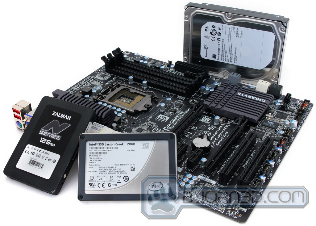
Intel Larson Creek 20GB SSD Overview
Here we have the newly released Intel Larson Creek 20GB SSD. This SSD was designed for the express purpose of a caching drive, and is meant to be used in conjunction with Intel Smart Response technology.


This SSD is just like the other Intel G2 Mainstream SSD drives, however the capacity is a minute 20GB. Though this may not seem like much, it is fine for its intended purpose–SSD caching.


The SSD uses the standard 2.5″ drive mounting options, and will fit any present SSD mounting provisions.

We opened up the unit to get a closer look. The PCB and component layout is very similar to the G2 Mainstream drives we have seen in the past


Here we can see that due to the decreased capacity of this drive, only one side has the NAND flash modules. These are 34nm Intel SLC chips supported by an Intel PC29AS21AB0 controller, and a ISSI 32MB Dram cache chip.
Intel smart response: SSD Caching Performance
One of the most interesting features with the Z68 chipset is the Intel Smart Response, which is essentially the SSD caching. The idea is very much like Windows 7 ReadyBoost where using a flash storage device to cache contents. However, unlike ReadyBoost, which uses flash drives as random disks, the SSD caching on the Z68 uses SSD to cache commonly used applications. This will result in faster application launch and system performance.
The SSD caching will not compete against real SSD in terms of performance but it will greatly enhance the system performance of a mechanical drive by adding a small size SSD. With commonly used data stored on the SSD, system will be more responsive and application will launch faster because SSD’s burst and sequential read performance is often two to five times faster than a mechanical drives.
To use SSD Cache, the following requirements must be met:
- 1 x SATA interface SSD drive capable of delivering read/write performance not slower than 100MB/s read and 150MB/s write.
- The minimum storage space needed for the SSD must be 20GB
- 1 x standard 7200RPM or 5400RPM HDD.
- A copy of Windows 7 operating system
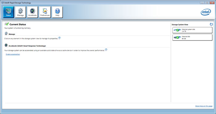
Setting up the SSD Caching is also extremely easy thanks to the latest Intel Rapid Storage program. Simply follow the guideline below:
- Perform a full SECURE Erase of the SSD with application from the SSD vendor.
- Format the HDD into NTFS, follow by a full format of the HDD.
- Set the Intel SATA ports to RAID mode.
- Install OS onto the HDD.
- Install Intel RST 10.5, then reboot.
- Enter RST 10.5 control interface, and click on the Accelerate button.
- Select the SSD drive, the amount of space to be used as cache, the HDD volume to accelerate, and the acceleration mode*, then click on OK to proceed.
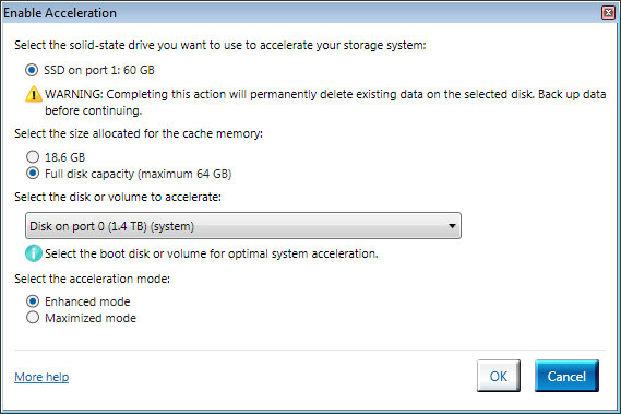
By default the a minimum of 18.6 GB of space on the SSD is needed to setup the SSD caching. Up to 64GB of space can be reserved for the cache. This is a good range as it offers enough space on the lower end for OS and 2-3 commonly used applications. Also, 64GB is a good number because if you can afford and SSD larger than 64GB, it would be much beneficial to use it as your primary drive for the best performance. After all, the data are still stored on the mechanical drive and if you ever need to access these data, you will not see the performance gain.
Intel offers two modes of caching mechanism: Enhanced and Maximized. While the read performance for both modes are roughly equal to the read performance of the SSD, the write performance for the Advanced Mode is a little slower than the slower of the two drives used (SSD or HDD). The write performance of the Maximized Mode on the other hand would be closer to the performance of the SSD. In addition, the Enhanced Mode offers stronger security as it utilize write-through strategy where data on the SSD and the hard disk are synchronized. In the event that the SSD is lost or damaged, no data is lost. The Maximized Mode utilizes write-back caching strategy where data are written to the disk in intervals. The risk here is that if the SSD failed or disconnected before the data has been written to the hard disk, the data will be lost.
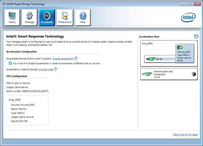
Switching the modes can be as simple as click of a button
As we can see from the image above, once the SSD Caching has been enabled, a partition will be created on the hard drive with the same storage capacity as the SSD (or the size on the SSD reserved for caching). The software shows the hard drive and the SSD are configured as RAID 0.

Something neat about the way Intel handles the SSD cache is that when an SSD is set up as the cache drive, it will not show up under Windows Computer Management. This will prevent user from accidentally format the SSD.
At the moment, Intel Smart Response Technology (IST) only support 1 HDD and 1SSD or 1 RAID Partition + 1SSD. In addition, the average read and write speed of the SSD must be at least 50% faster than the hard drive in a single HDD+SSD combination, and at least 100% faster for RAID 0 to see the performance gain.
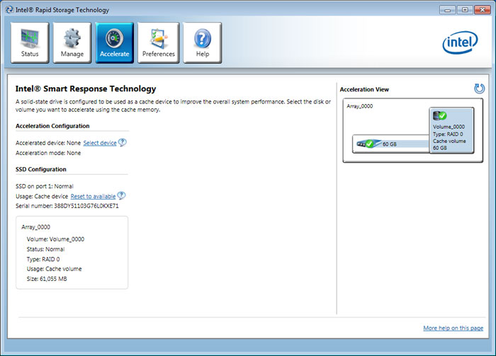
If you ever decide to stop using the SSD Caching, simply click on the “Reset to available” and the SSD can be used again as regular drive.
PCMARK VANTAGE
PCMark Vantage is the latest system benchmark tool from Futuremark. The benchmark consists of tests such asapplication launches, file searches, web browsing, video playback, photo editing, and gaming.
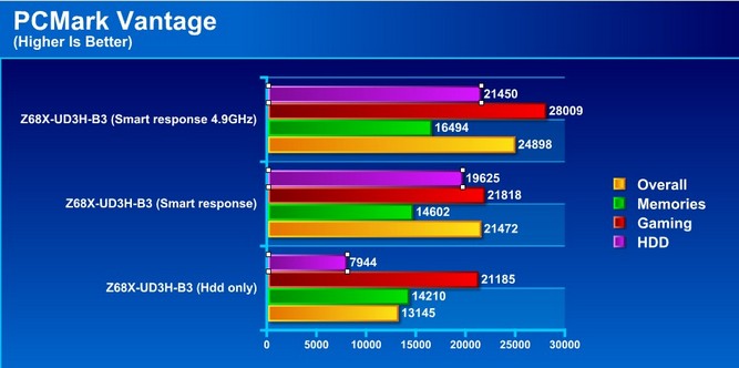
In the PCMark Vantage test we paid particular attention to the HDD Suite and we were surprised to see that the addition of the SSD as a caching device increased the gaming aspect of the test as well. The truly impressive result is the huge increase in HDD performance with the SSD on board as a caching device.
Windows boot-up Performance
Here we test the time it takes from the windows loading screen until we are at the desktop. this will show us exactly what kind of performance gain we can see from the application of the Smart Response technology.
| Windows 7 Ultimate Boot-Up Time | |
| Western Digital Velociraptor | 23.2 Seconds |
| Western Digital Velociraptor + Intel 20GB SSD Smart Response | 14.9 Seconds |
From these two simple tests there is a clear comparison between a system that would be using just a SATA Hard Drive or the same Hard Drive with a 20GB Intel Larson Creek SSD. There is once again a noticable performance increase making it possible for Windows 7 Pro to boot about 9 seconds faster than a system with just a Hard Drive. This performance increase happens after the system performs the same task twice in a row. This should also be noticed in other applications that might be taking advantage of the SSD Caching
Switchable Graphics
The GIGABYTE Z68X-UD3H-B3 is capable of switchable graphics. Switchable graphics technology allows usage of the integrated GPU for its power saving capabilities when heavy 3D loading is not necessary, and a seamless transition to the discrete GPU when 3D loading is necessary.
Setup is rather easy–all that is required is to plug the display into one of the display ports from the I/O panel of the motherboard. This will allow all basic display functions, and once users are within the operating system, they can install the discrete graphics card driver and Lucid Virtu software. Once installed, all operations of 2D rendering and video playback or any other non graphics intensive usage will be rendered by the integrated GPU. Once a game or 3D program is initiated for which the Virtu software has a profile, the discrete GPU will take over. All of this happens without swapping the display cable, and users do get similar performance as the discrete GPU, but with the power savings of the integrated graphics when heavy 3D rendering is not needed.

Lucid Virtu
This is where the magic happens. The Lucid Virtu is the intermediate software that switches graphics processors from the integrated GPU to the discrete GPU on the fly, depending upon the program that is running. This feature can be enabled or disabled as deemed necessary.
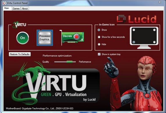
Here we can see Virtu enabled. This allows the GPU switching to activate.
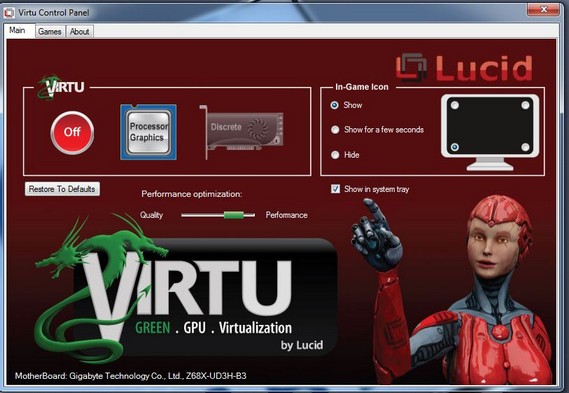
Virtu can be disabled with the press of a button. We experienced some issues with the GPU switching technology. For example, when we attempted to access the NVIDIA Control Panel with the display cable connected to the motherboard’s port, we received the following message:
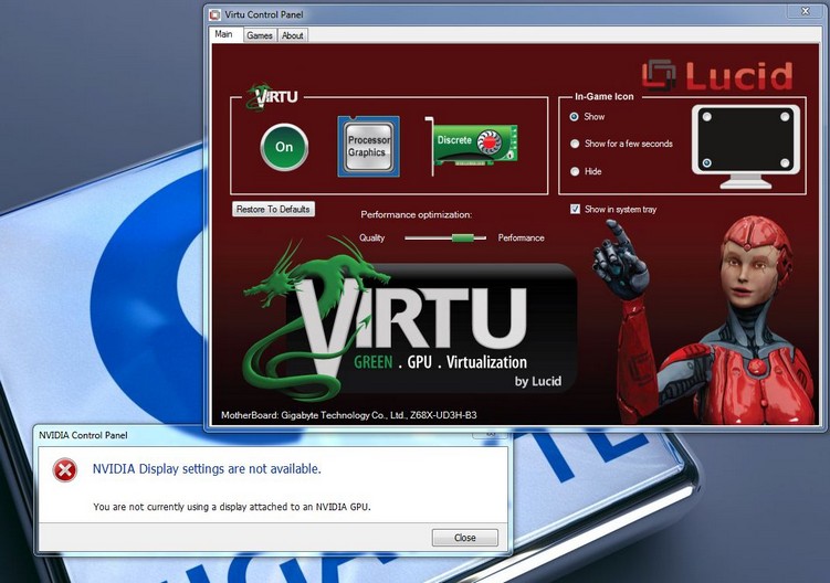
This is an issue as the only way to access the display control panel is to connect the display to the discrete graphics card. By doing that, users lose the power savings gained by using the integrated GPU in low load environments. We also observed frequent crashing of the iGPU software, an issue we hope will be remedied soon. This problem presents a huge stumbling block for the platform, as the GPU switching ability is considered one of its key features.
Most may ask what advantages there are besides the power savings to have access to the integrated GPU on the Sandy Bridge processor. The Sandy Bridge processor has the capability to run Intel QuickSync technology as well. QuickSync will be discussed later in the review. With GIGABYTE’s graphics switching technology, even if a user plugs the display into the discrete card, they can still access the Integrated GPU for processing purposes such as QuickSync operations.
Intel Quicksync
The Sandy Bridge CPU has a GPU imbedded into the die, and while it works well for all of our basic desktop needs, there is another more powerful use for this integrated GPU. Intel QuickSync allows for hardware accelerated video transcoding.
To test this we set up a 5.8GB 1080P MKV file to be transcoded to a H.264 MP4 1080P 8192kbps.
For testing we will compare standard x86 transcoding, which uses the physical processor cores to transcode the video file. then we will test with the Quick Sync technology and lastly with Nvidia CUDA on a GeForce GTX 580 to compare processing time and quality of the output file.
| Transcode method | Time |
| Intel Core i7-2600K x86 | 33:31 |
| Intel Core i7-2600K Quick Sync | 16:28 |
| NVIDIA GeForce GTX 580 Cuda | 31:49 |
As we can see from the testing, QuickSync is very fast and will allow for a huge increase in productivity for anyone who regularly performs these sort of operations. Additionally, when testing this capability, we were able to run full speed graphical or system benchmarks without any delay in performance.
Output file quality
After transcoding was completed we observed all copies of the transcoded file and to my surprise there were some differences. the differences are listed below.
CPU x86: This copy was the cleanest. It took the longest to transcode but was comparable to the source file with no corruption artifacts or distortion.
Nvidia CUDA: This copy had compression blocks and artifacts at random times, especially in darker scenes. It did not ruin viewing, but for anyone looking for the best quality this would likely annoy those users.
Intel QuickSync: This copy was very clean and extremely close to the source file, but on occasion, there was a slight softening of color and an occasional blurring. The distortion was barely noticeable, however.
Special Features
Z68 Express Chipset New Features
- Quick Sync media accelerator support with with Intel’s second generation Core architecture. Most of Z68 board that have the integrated graphics support are enabled with LucidLogix Virtu™ GPU Virtualization technology, therefore, for gamers who require high-resolution gaming and they still able to enjoy the 3D graphic experience with 2nd generation Intel® Core™ processors. This is also a great salutation that GIGABYTE is offering to the high end users/gamers.
- Support for SSD caching technology called Smart Response. This option allows users to speed up their storage system by using a standard SATA Hard Drive with a standard SATA SSD. The SSD will work as a fast cache memory for the hard drive.
- GIGABTYE Touch BIOS™ (Patent Pending)
GIGABYTE Z68X-UD7-B3 Other Features
- GIGABYTE Ultra Durable™ 3 design with 2x Copper PCB to provide the stability, reliability and longevity essential to meet the power needs of high-end processors and other components running today’s most demanding applications and games.
- CrossFireX™ and Nvidia® 3-Way SLI™ support for ultimate gaming experience.
- Matte Black color PCB offering a stylish new outlook that blends itself to decoration and case mods.
- Unique GIGABYTE 3x USB Power design with On/Off Charge USB ports to offer faster battery charging for iPhone, iPad and iPod devices.
- GIGABYTE patented DualBIOS™ technology delivering the highest level of failure protection.
- Driver MOSFET Solution
- 3TB+ HDD Support
An Innovative New Way to Modify BIOS Settings
 Navigating through the BIOS to change system settings can be a daunting task for users not familiar with control “F”functions and mouse-less navigation. While some EFI BIOS try to address this with a mouse friendly environment, many implementations still lack a certain ease-of-use necessary for most people. With GIGABYTE Touch BIOS™, GIGABYTE engineers have completely re-imagined how users can interact with their BIOS, allowing for a more intuitive user experience. In fact, with a touch screen monitor, GIGABYTE Touch BIOS™ is as easy to use as most apps on your iPhone.
 GIGABYTE Z68 series motherboards are equipped with the much anticipated Intel® Smart Response Technology, allowing users to experience system performance similar to SSD only systems. Intel® Smart Response technology works by using intelligent block-based caching of frequently used applications to improve system performance and responsiveness. In fact, GIGABYTE Z68 motherboards with Intel® Smart Response Technology are able to outperform hybrid drive systems by more than 2X (PC Mark Vantage) and HDD-only systems by as much as 4X (PC Mark Vantage).
* 4X+ Faster than HDD-only system in PC Mark Vantage(HDD Score)

The GIGABYTE EZ Smart Response utility is a simple application that allows users to quickly and easily configure their system for Intel® Smart Response Technology. In the past, enabling Intel® Smart Response meant users needed to enter the BIOS in order to configure their system for RAID mode, which then required a complete reinstall of the operating system. Once that processes was complete, users then needed to install the Intel® Rapid Storage Utility as well as configure Intel’s Smart Response Technology. GIGABYTE EZ Smart Response does all of this automatically, without users having to perform a complicated install process. This allows them to quickly and effortlessly enjoy a significant boost in system performance…more
Built-in Visuals GIGABYTE Z68 motherboards offer support for several 2nd generation Intel® Core™ Built-in Visual Features.
Intel® Quick Sync Video
Up to 2X faster media processing than any other solution for incredibly fast conversion of video files for portable media players or online sharing.
Intel® InTru™ 3D
Users can enjoy the ultimate 3D visual experiences–seamlessly–from their PC. Now you they can watch their favorite 3D movies with Blu-ray Stereo 3D playback using active shutter 3D glasses. It delivers it all in 1080p full, high-definition resolution on the TV over HDMI 1.4.
Intel® Insider
Allows users to view premium 1080p HD content on their GIGABYTE Z68 series system.
Switchable Graphics with LucidLogix Virtu GPU Virtualization  GIGABYTE Z68 motherboards are enabled with LucidLogix Virtu GPU Virtualization technology which allows users to dynamically switch between their built-in graphics and their high-end, 3D discrete graphics cards. This is ideal for gamers who require high-resolution gaming and still want to enjoy the built-in media features of 2nd generation Intel® Core™ processors. In so doing, switchable graphics helps to dramatically reduce PC graphics power consumption.


GIGABYTE 6 series motherboards incorporate an Intel® approved Intersil PWM controller that is VRD 12 (Voltage Regulator Down) compliant. This means that it offers new features that include SerialVID (SVID) which transfers power management information between the processor and voltage regulator controller, allowing more robust and efficient signaling control between the CPU and PWM controller – hence, delivering a more energy efficient platform.


A traditional Voltage Regulator Module (VRM) consists of a Choke, Capacitors, MOSFETs and a Driver IC. By incorporating the MOSFETs and driver IC in accordance with the Intel® Driver-MOSFET specification, we can achieve higher power transfer and increased efficiency at higher switching frequencies to satisfy the growing power requirements of today’s processors. Driver-MOSFETs also help to reduce VRM real estate requirements in the CPU zone.


Intel® Quick Sync Video
Intel® Quick Sync Video provides breakthrough media processing for incredibly fast editing and sharing.
Intel® InTru™ 3D
2nd Generation Intel® Core™ Processors offer an outstanding Blu-Ray Stereo 3D experience in full high definition resolution (1080p) with HDMI 1.4.
Intel® Advanced Vector Extensions (AVX)
Increases the performance of Accelerated Floating Point and Vector Computing Intensive Applications with minimal power gains.

All of GIGABYTE’s 2011 motherboards feature higher capability audio solution with 108dB Signal-to-Noise ratio (SNR) playback quality to deliver high-performance, multi-channel HD audio. SNR is a comparison of the amount of signal to the amount of noise such as hiss present in the signal (expressed in Decibels). A higher SNR equals a better audio experience. For example, 108dB, is a high audio specification, as this means the audio signal is 108dB higher than the level of the noise.
")
GIGABYTE DualBIOS™ is a patented technology that automatically recovers BIOS data when the main BIOS has crashed or failed. Featuring 2 physical BIOS ROMs integrated onboard, GIGABYTE DualBIOS™ allows quick and seamless recovery from BIOS damage or failure due to viruses or improper BIOS updating. In addition, GIGABYTE DualBIOS™ now supports 3TB+ (terabyte) hard drive booting without the need for partitioning, and enables more data storage on a single hard drive.


The GIGABYTE Ultra Durable™ 3 design features twice the copper for both the power and ground layers of the PCB, dramatically lowering system temperature by efficiently spreading heat from critical areas of the motherboard (such as the CPU power zone) throughout the entire PCB. GIGABYTE’s Ultra Durable™ 3 also lowers the PCB impedance by 50%, which helps to reduce electrical waste and further lowers component temperatures. A 2x Copper layer design also provides improved signal quality and lower EMI (Electromagnetic Interference), providing better system stability and allowing for greater margins for overclocking…more

Note: Due to certain mobile phone limitations, users may need to connect the mobile phone to their PC before the PC enters S4/S5 mode to enable a quick charge from non On/Off Charge USB ports. Charging results may vary by model.


Turbo XHD function only enabled for the SATA controllers integrated in the Intel Z68/P67/H67 Chipset.


 |
Smart QuickBoot |
 |
Smart DualBIOS Smart personal reminder of PC passwords. |
 |
Smart QuickBoost* One-click Overclocking |
 |
Smart Recorder Your PC’s Watch Dog |
 |
Smart Recovery 2 Allows you to go back in time on your PC and retrieve lost files |
 |
Smart TimeLock Time Controller for your PC. |
* Whether SMART QuickBoost is supported depends on the motherboard model.

GIGABYTE Cloud OC is a free overclocking application that facilitates PC overclocking through any web browsing capable device such as a smart phone, iPad, iPhone, Netbooks or notebook PC. Being browser based, it connects via wireless Internet, Bluetooth or through an Ethernet cable, and its many functions are categorized into three tabs: Tuner, System Info and Control…more


Note: GIGABYTE motherboards do not include a Bluetooth® receiver; the addition of a 3rd party Bluetooth receiver is required.

Dolby Home Theater® places listeners in the middle of the action, giving their PCs a powerful set of tools to deliver a cinema-style experience in vivid surround sound.
- Delivers vivid surround sound for music, movies, and games, using two to eight speakers or any set of headphones
- Designed to automatically deliver the best possible listening experience

Specifications
Even though the GIGABYTE Z68X-UD7-B3 motherboard came with a NF200 chip and was designed for mainly gamers using multiple GPU discreet graphics, it is still a bit of a disappointment that GIGABYTE left out the Integrated Graphics and VIRTU option on the UD7. The GIGABYTE Z68X-UD3H-B3 takes care of this issue by having multiple display outputs on the rear side of the motherboard to take advantage either the Intel integrated graphics on the new Sandy Bridge processors, or use Discreet graphics from Nvidia or AMD. Other than that, the UD3H-B3 is not much different from the UD7 other than the missing NF200 chip and the extra PCI-Express slot. Of course there are different components and chips used on this motherboard, but the overall performance and stability should still be there.
| Specification | GIGABYTE Z68X-UD3H-B3 |
|---|---|
| CPU |
(Please refer “CPU Support List” for more information.) |
| Chipset | Intel® Z68 Express Chipset |
| Memory |
(Please refer “Memory Support List” for more information.) |
| Onboard Graphics | Integrated in the Chipset:
|
| Audio |
|
| LAN | 1 x Realtek RTL8111E chip (10/100/1000 Mbit) |
| Expansion Slots |
|
| Multi-Graphics Technology | Support for ATI CrossFireX™/NVIDIA SLI technology * The PCIEX16 slot operates at up to x8 mode when ATI CrossFireX™/NVIDIA SLI is enabled. |
| Storage Interface | Chipset:
Marvell 88SE9172 chip:
|
| USB | Chipset:
2 x Etron EJ168 chips:
|
| IEEE 1394 | VIA VT6308 chip:
|
| Internal I/O Connectors |
|
| Back Panel Connectors |
|
| I/O Controller | iTE IT8728 chip |
| H/W Monitoring |
|
| BIOS |
|
| Unique Features |
|
| Bundle Software | Norton Internet Security (OEM version) |
| Operating System | Support for Microsoft® Windows® 7/Vista/XP |
| Form Factor | ATX Form Factor; 30.5cm x 24.4cm |
| Remark |
|
Unboxing the GIGABYTE Z68X-UD3H-B3


The box is a normal retail package. The front, back, and sides are covered with icons and marketing slogans to try to push all of the special features. A large part of the front cover highlights the TouchBIOS technology, which we found a little misleading due to the fact that the BIOS is a standard Award BIOS and the TouchBIOS is a Windows-based application, a fact which most users will not know until they read about it or buy the board. Users will also find that like all GIGABYTE motherboards, this unit carries the 3 year warranty for their US and Canada customers.


Once the box is open and everything is unpacked the user will see what they have to work with. The accessory bundle is sparse–only a few SATA cables, an SLI Bridge, a Manual, and an I/O Shield are included with the board. Even though this is a mainstream board, the inclusion of items such as a USB 3.0 bracket to support the onboard header would have made this a more attractive package. Another seemingly standard fair item would be a USB 2.0 bracket to support some of the 4 onboard headers that are found at the lower edge of the motherboard.
Overview of the Z68X-UD3H-B3


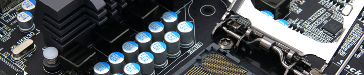
This board has many features for a mainstream motherboard. The large size of the chipset heatsink means that even when placed under a couple high-end graphics cards, this heatsink should keep the chipset cool enough to avoid issues. The PWM area is not adorned with 24 phases for the CPU or an elaborate heatpipe cooler since this is a mainstream board. One feature that really excited us is that GIGABYTE finally got the PCI-E spacing correct on this board. The board has PCI-E x1 slots in between the x16 and x8 slots. This spacing prevents any heat issues from arising due to a multi-GPU configuration in which the bottom card would dissipate heat onto the top card, potentially overheating it. The board also uses GIGABYTE’s Ultra Durable 3 components which include the sturdy 2 oz copper PCB and high quality capacitors and components to allow for cooler operation and longer life expectancy.


Taking a quick once over on the rest of the board, there are plenty of connectivity option included. There are more than enough USB ports and headers, 2 PCI slots for any legacy components, and also 3 PCI-E x1 slots. All connections are well placed to make installation rather simple, as everything should be easy to hookup. One thing to note is that this being a mainstream product means that some features a user may come to expect are not included. One of the most common that we were surprised we did not see was the lack of the onboard PC speaker and 2 digit post code display. However, it would have been nice for GIGABYTE to include a POST beep speaker, to help during error diagnosis.

The I/O panel has almost every graphics port necessary, including DVI, HDMI, DisplayPort, and the aging VGA. Additionally, the inclusion of optical audio out is a welcome sight for anyone running this as a home theater setup.
A closer Look


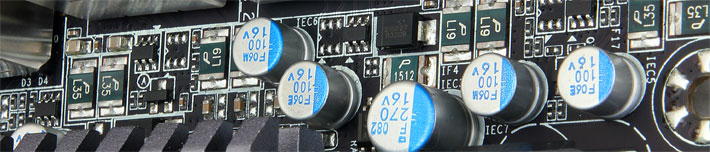
As we start to look deeper into what makes this board run, we see many components and controllers. Starting at the bottom left, we see an ITE controller chip used for control of I/O functionality. The lower edge of the board has a VIA chipset VT6308 which is used to control the 1394 ports. In the same area we see two Etron EJ168 chipsets, which control the USB 3.0 port functionality (2 ports per controller). Along the I/O side of the board are two different Realtek Chipsets–the RTL8111E controls the Gigabit LAN port, and the ALC889 controls the high Definition audio outputs. Also notice the high quality Japanese solid state capacitors which are part of the GIGABYTE Ultra Durable 3 design. Due to the amount of space the display outputs occupy on the I/O panel, many of the USB ports had to be relocated to onboard headers at the lower edge of the motherboard.


Above we move upward on the board and we find the small rectangles below the primary PCI-E slot. These are the electronic switches which split the 16 available PCI-E lanes to dual x8 bandwidth for the two PCI-E x16 slots when a card is installed into the 2nd PCI-E x16 slot. Below the CPU socket are the dual-BIOS chips. The use of dual-BIOS offers worry-free tuning and overclocking.


Last but definitely not least we have the PWM. It is a 4+2+1 design, which means we have the base 4 phases for the VCC or CPU Vcore, then we have 2 phases for the VTT/memory controller and the remaining single phase is to feed power to the onboard graphics processor built into the CPU.

The cooler for the PWM on this board is cooled by a aluminum heatsink bearing a resemblance to the other GIGABYTE 6 series motherboard cooling components. It uses a thermal pad to help transfer the heat to the heatsink and standard pushpin/spring combo to assist with mounting pressure. Usually, screw mounting is desired as it allows for much better contact and even pressure across the mounting surface, but considering that this is a mainstream board, it should do just fine as installed.
BIOS
Main Page


MB Intelligent Tweaker (M.I.T.)


It is interesting to see that while the BIOS for the GIGABYTE Z68X-UD7-B3 does not differ a lot from the P67A-UD7 or UD4, the sections that have options for different settings usually provide more options for the user. This is why the Z68X-UD7-B3 motherboard has more control over the settings in a system. The P67A-UD4 has all the necessary options that most users will require. For instance, the UD4 only has AUTO, Enabled and Disabled options for the Load-Line Calibration, while the UD7 has AUTO, Disable, Level 1, and Level 2 settings. To sum it up, the UD7 is a motherboard where everything can be fine tuned, while the UD4 has is a board for coarser adjustments. The UD4 and UD7 also allow for fine tuning each core’s multiplier, for the processor, especially with Turbo enabled.
Advanced BIOS Features


Integrated Peripherals, Power Management Setup & PC Heath Status


Overclocking

The Sandy Bridge architecture does not allow for much in the way of base clock overclocking. In order to really push the limits, users need a K series CPU with an unlocked multiplier. These CPUs will run in excess of 4.5GHz on air. Some will run up to 5+GHz on water cooling or better.
Overclocking past 4.5-4.8 GHz+ will require adjustment of voltages and enabling the CPU PLL Overvoltage option in the BIOS. For the overclocking testing we will be pushing as far as we can on air cooling, though readers should keep in mind that for optimal performance and least possible chance of component failure, we recommend the best cooling possible.
Another Note is that no matter how good the cooling solution, some CPU’s are limited. Reference the numbers provided by ASUS below.
From 100 Samples tested the following was possible with full stability.
1. Approximately 50% of CPUs can go up to 4.4-4.5 GHz
2. Approximately 40% of CPUs can go up to 4.6-4.7 GHz
3. Approximately 10% of CPUs can go up to 4.8-5 GHz (50+ multipliers are about 2% of this group)
Our Sample would reach a maximum speed of 4.9GHz anything past that and it would boot but would not pass stability testing. We confirmed that this was limited by the CPU and not the board by running it on liquid nitrogen cooling and a P67 board. This means that even though this is a mainstream board, users will be able to overclock in excess of 4.8GHz and run without any issues with thermals or stability.
Important note: Any level of overclocking can cause component failure. Please exercise caution when attempting any level of overclock on system components.
Temperatures

The temperatures were recorded with Realtemp while running Wprime 1024 right before the end of the 5th run. The results were recorded carefully. After the results were recorded, we waited for 30 minutes before taking Idle temperature measurements. The results were as follows:
| Configuration | Temperature (Idle/Load) |
| Z68X-UD3H-B3 OC (4.9GHz) | 41C/72C |
| Z68X-UD3H-B3 | 36C/65C |
As we found water cooling would be a much better solution to keep temperatures lower to avoid long term issues from the higher temperatures. The Thermaltake Frio OCK cooler definitely surprised us as it held the load and was completely stable during many runs and benchmarking at 4.9GHz the whole way.
Power Consumption

The power consumption was tested while running Wprime 1024 for a few minutes at stock settings. The results were recorded carefully with a Kill-A-Watt power consumption measuring tool at the wall. After the results were recorded, we waited for yet another few minutes minutes before taking Idle power consumption measurements.
| Configuration | Power Consumption (Idle/Load) |
| Z68X-UD3H-B3 (4.9GHz) | 243W/354W |
| Z68X-UD3H-B3 | 210W/331W |
The power consumption is not with GPU usage. This is with CPU/system loading but nothing graphically intensive in order to provide the most accurate results by not ramping up the GPU, which will pull significantly more power.
Testing & Methodology

We’ve expanded our testing suite considerably for the Z68 chipset, and will continue to use the same methods for most of the motherboards and CPU’s we test. In the interests of thoroughness and accurate results, we run each test at least three times, and some tests more than that. We average the total of all the tests from each benchmark then report the average here.
The OS we use is Windows 7 Pro 64bit with all patches and updates applied. We also use the latest drivers available for the motherboard and any devices attached to the computer. We do not disable background tasks or tweak the OS or system in any way. We turn off drive indexing and daily defragging. We also turn off Prefetch and Superfetch. This is not an attempt to produce bigger benchmark numbers. Drive indexing and defragging can interfere with testing and produce confusing numbers. If a test were to be run while a drive was being indexed or defragged, and then the same test was later run when these processes were off, the two results would be contradictory and erroneous. As we cannot control when defragging and indexing occur precisely enough to guarantee that they won’t interfere with testing, we opt to disable the features entirely.
Prefetch tries to predict what users will load the next time they boot the machine by caching the relevant files and storing them for later use. We want to learn how the program runs without any of the files being cached, and we disable it so that each test run we do not have to clear pre-fetch to get accurate numbers. Lastly we disable Superfetch. Superfetch loads often-used programs into the memory. It is one of the reasons that Windows occupies so much memory. Vista fills the memory in an attempt to predict what users will load. Having one test run with files cached, and another test run with the files un-cached would result in inaccurate numbers. Again, since we can’t control its timings so precisely, it we turn it off. Because these four features can potentially interfere with benchmarking, and and are out of our control, we disable them. We do not disable anything else.
Test Rig
| Test Rig | |
| Case | Thermaltake Level 10 GT |
| CPU |
Intel Core i7 2600K |
| Motherboard |
Gigabyte Z68X-UD3H-B3 |
| Ram | 4GB Kingston 1600MHz CL 7 (7-7-7-24) |
| CPU Cooler |
Thermaltake Frio OCK |
| Hard Drive | Western Digital Velociraptor 300GB |
| SSD |
Intel 20GB SLC Larson Creek SSD Intel 510 series SATA III/6G 120GB |
| Optical | ASUS BD-Rom |
| GPU |
Nvidia GeForce GTX 580 |
| Case Fans |
Front (intake): 200 x 200 x 20 mm ColorShift Fan x 1 (600~800RPM, 13~15dBA) Rear (exhaust): 140 x 140 x 25 mm Turbo Fan (1000PRM, 16 dBA) Top (exhaust): 200 x 200 x 30 mm ColorShift Fan (600~800RPM, 13~15dBA) Side (intake): 200 x 200 x 30 ColorShift Fan (600~800RPM), 13~15dBA) |
| Additional Cards |
N/A |
| PSU |
Thermaltake Toughpower Grand 1200W |
| Mouse | Thermaltake esports Black gaming mouse |
| Keyboard | Thermaltake Meka G1 mechanical gaming keyboard |
Test Suite
We will use the following applications to test the performance of the Motherboard. Benchmarks
| Benchmarks |
|---|
| PCMark Vantage |
| Windows Boot Time |
| Cinebench R10 |
| Cinebench R11.5 |
| 3DMark 11 |
| 3DMark Vantage |
| Crysis Warhead |
| Just Cause 2 |
CINEBENCH R10 AND R11.5
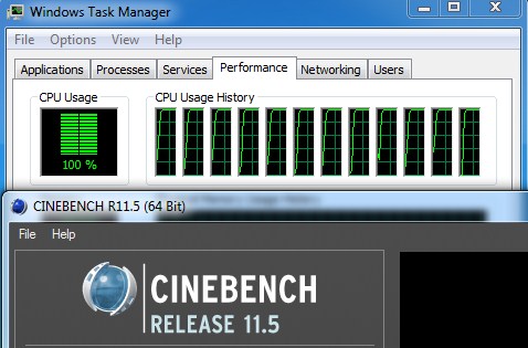
“CINEBENCH is a real-world test suite that assesses your computer’s performance capabilities. MAXON CINEBENCH is based on MAXON’s award-winning animation software, CINEMA 4D, which is used extensively by studios and production houses worldwide for 3D content creation. MAXON software has been used in blockbuster movies such as Spider-Man, Star Wars, The Chronicles of Narnia and many more. MAXON CINEBENCH runs several tests on your computer to measure the performance of the main processor and the graphics card under real world circumstances. The benchmark application makes use of up to 16 CPUs or CPU cores and is available for Windows (32-bit and 64-Bit) and Macintosh (PPC and Intel-based). The resulting values among different operating systems are 100% comparable and therefore very useful with regard to purchasing decision-making. It can also be used as a marketing tool for hardware vendors or simply to compare hardware among colleagues or friends.”
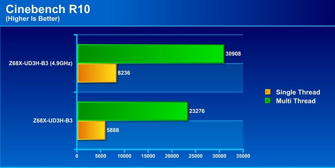
There are visible increases in performance when we overclocked the CPU, and as seen, both the multithreaded and single threaded performance received a significant bump.
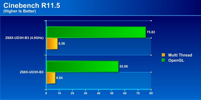
Similar results are observed when running Cinebench R11.5.
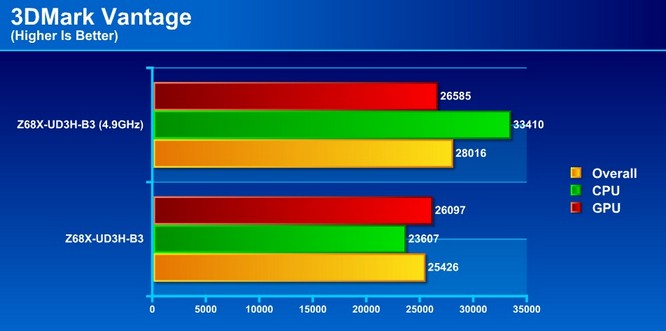
3DMARK VANTAGE

For complete information on 3DMark Vantage Please follow this Link:
www.futuremark.com/benchmarks/3dmarkvantage/features/
The newest video benchmark from the gang at Futuremark. This utility is still a synthetic benchmark, but one that more closely reflects real world gaming performance. While it is not a perfect replacement for actual game benchmarks, it has its uses. We tested our cards at the ‘Performance’ setting.
3DMARK 11
![]()
3Dmark 11 is the newest in futuremark’s suite of benchmarking utilities. Its a fully capable DirectX11 benchmark which also stresses and analyzes the system performance as a whole to simulate a heavy rendering environment such as a high end game or other app the end user may run. This benchmark was run with Performance settings 5 times and all runs were averaged for the result below.
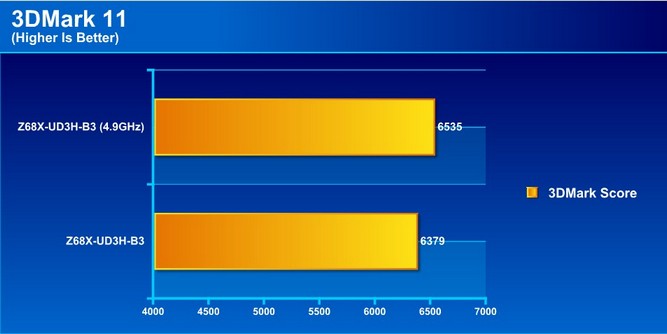
3DMark Vantage and 3DMark 11 both showed a slight increase in graphics performance, though the overall score increase could also be from better multi-threaded CPU scaling and better PCI-Express scaling. Either way, users can expect slight performance increase in 3D related applications with the Z68 chipset.
CRYSIS WARHEAD

Crysis Warhead is the much anticipated standalone expansion to Crysis, featuring an updated CryENGINE™ 2 with better optimization. It was one of the most anticipated titles of 2008.
We ran Warhead using gamer’s setting at resolution of 1920X1080 and DirectX 10. We tested both no AA.
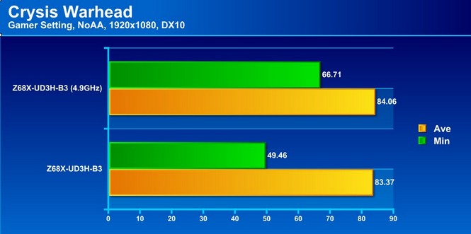
JUST CAUSE 2

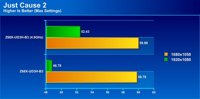
Crysis Warhead and Just Cause 2 show that the increase in CPU frequency gave a slight bump to the performance of graphically intensive applications. However, the overall effect will most likely not be noticeable in performance gaming.
CONCLUSION
The Z68X-UD3H-B3 is a great idea and is executed well but there are some stumbling points for the motherboard. One of the major features of the board–the GPU Switching feature–is based on the Lucidlogix Virtu software, which works most of the time, but can cause major frustration when it fails. With some time and optimization, this could turn into a seamless technology, usable in our every day environment which can save power and provide performance need all in the same package.
The motherboard performs very well considering its mainstream niche, and overclocks surprisingly well with no stability issues. Additionally, Intel Smart Response technology gives users another way to increase performance substantially without a large investment.
The GIGABYTE TouchBIOS was a pleasure to test and performed without issue. It is an excellent addition by GIGABYTE to give users who are not comfortable working within the motherboard BIOS a chance to test and tune their system configuration the same way many enthusiasts do from an easy to use graphical interface.
The overall design of the board is good for a mainstream board, and has adequate slot spacing to allow cooling of Dual GPU configurations. The included chipset cooling is adequate to keep the chipset cool even when large hot graphics cards are placed above.
| OUR VERDICT: GIGABYTE Z68X-UD3H-B3 | ||||||||||||||||||
|
||||||||||||||||||
| Summary: The GIGABYTE Z68X-UD3H-B3 comes with many features packed within a mainstream package with a mainstream price tag to match. Though its Virtu software has some bugs and it unfortunately has no GUI BIOS, for its performance and value, it earns the Bjorn3D Silver Bear Award. |