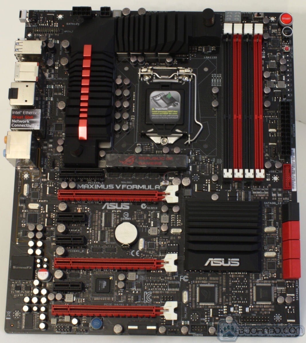
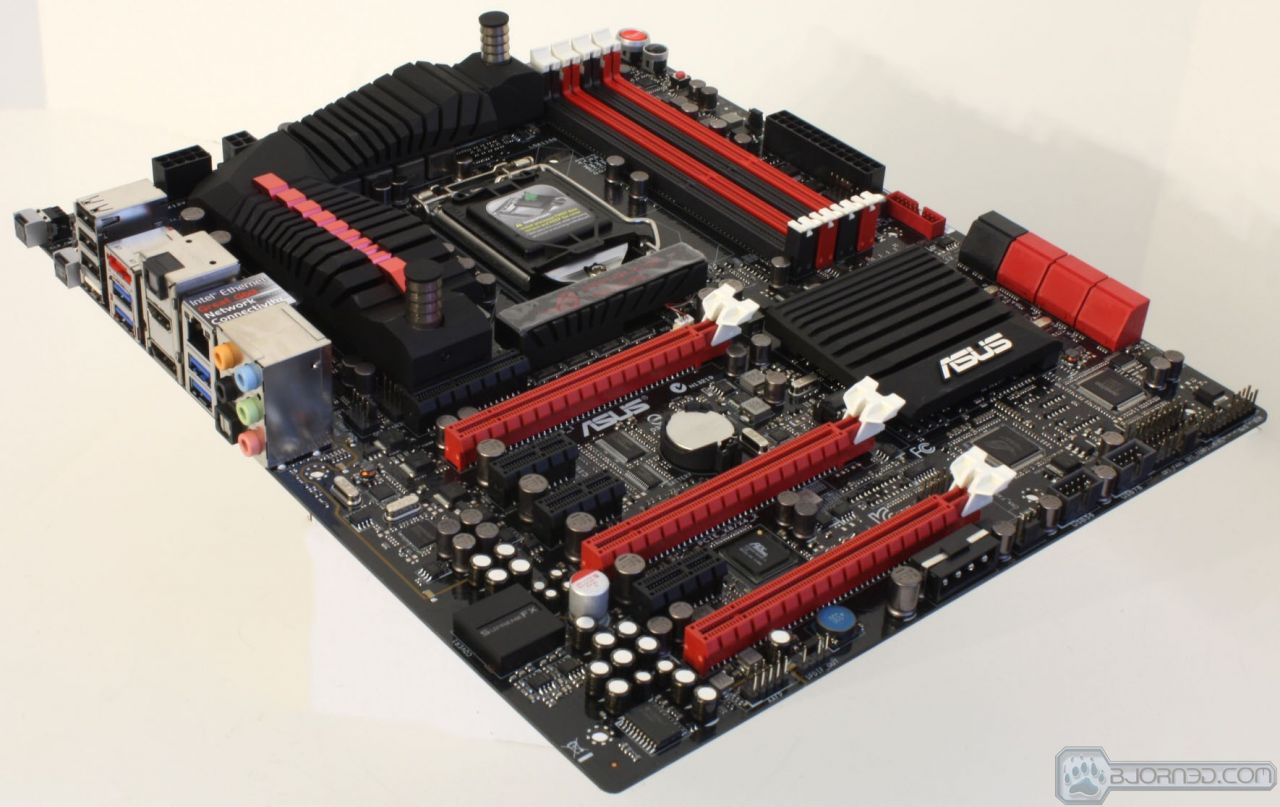
Overview of the ASUS Maximus V Formula
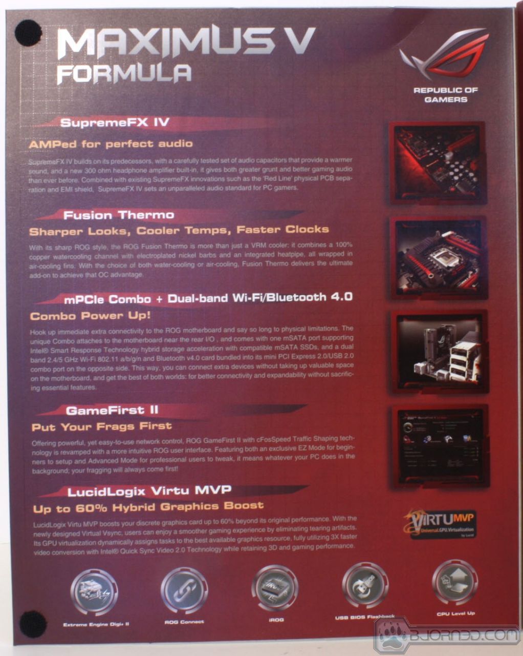

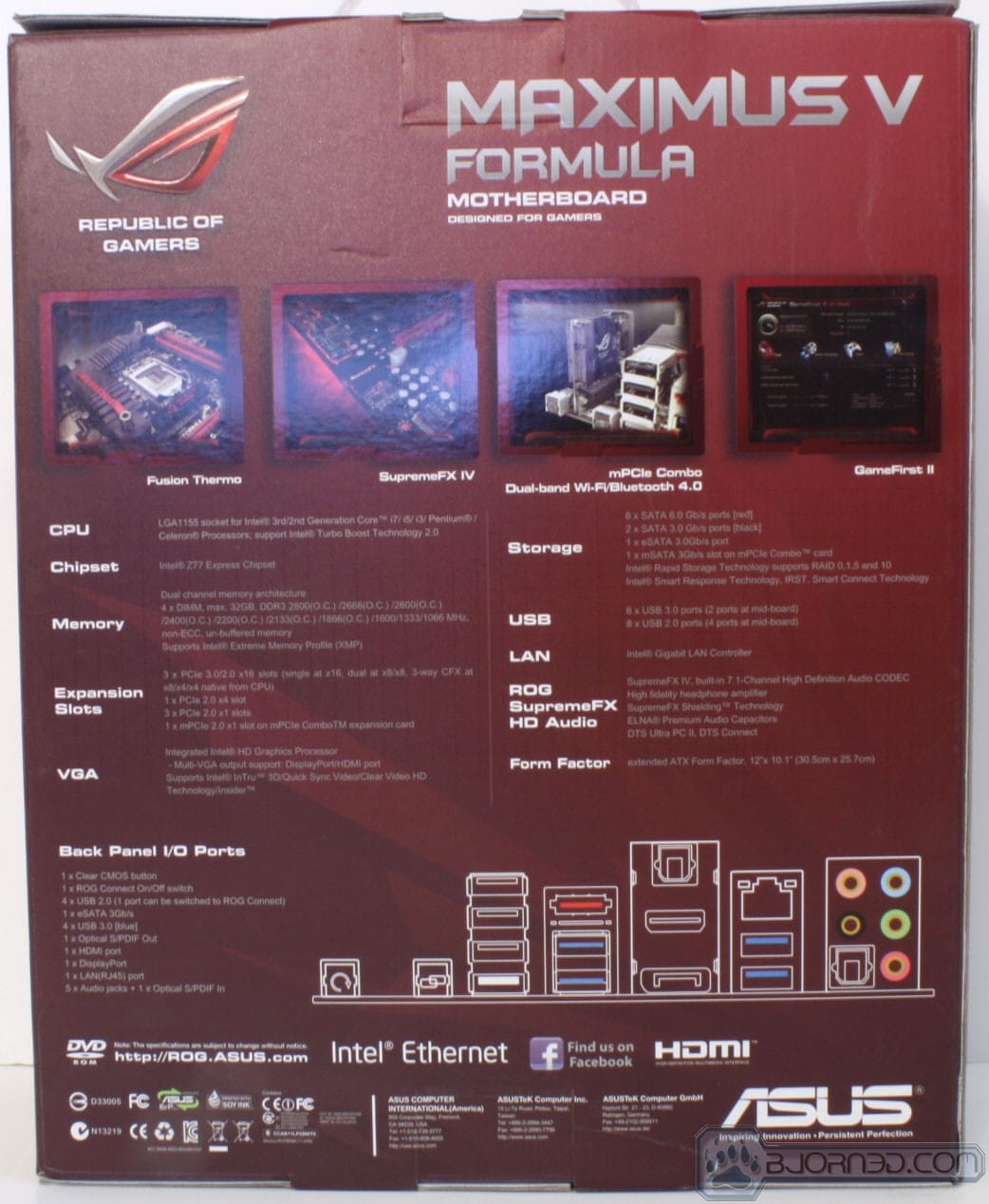

The Packaging is very much like other ROG products we have seen many times before. It’s a full red packaging, flip open cover showing the board along with many of the key features. The rear shows the IO layout along with small highlights of some key features.
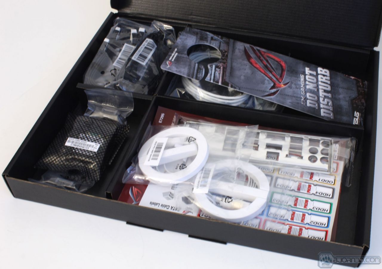
Inside the box there are two black boxes one of which being the mainboard box, and the other being the accessory box which holds the plethora of accessories that come with the board.

Click Image For a Larger One
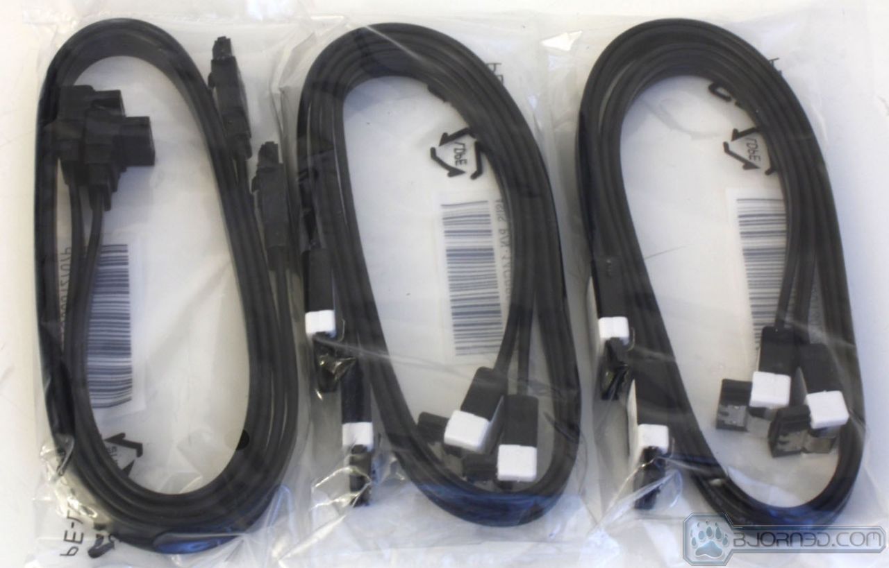
- SATA Cables
- ROG Connect Cable
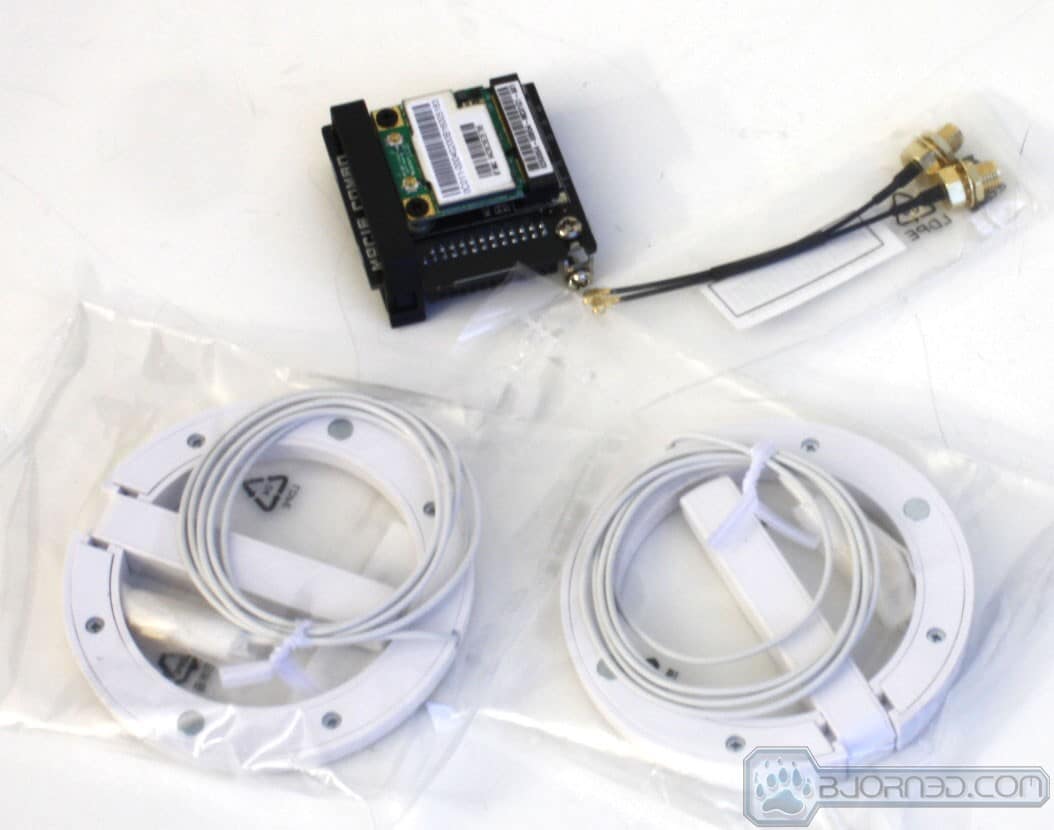
- mSATA/mPCI-E Combo card (w/pre-installed WiFi/BT4.0 Card)
- WiFi/BT 4.0 Antennae
- Qconnect front panel connectors
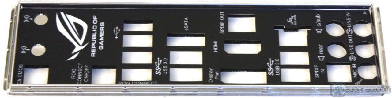
- IO Shield
- SLI Ribbon Cable
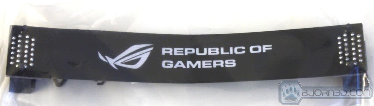
- ROG door Hanger
- Cable labeling Stickers
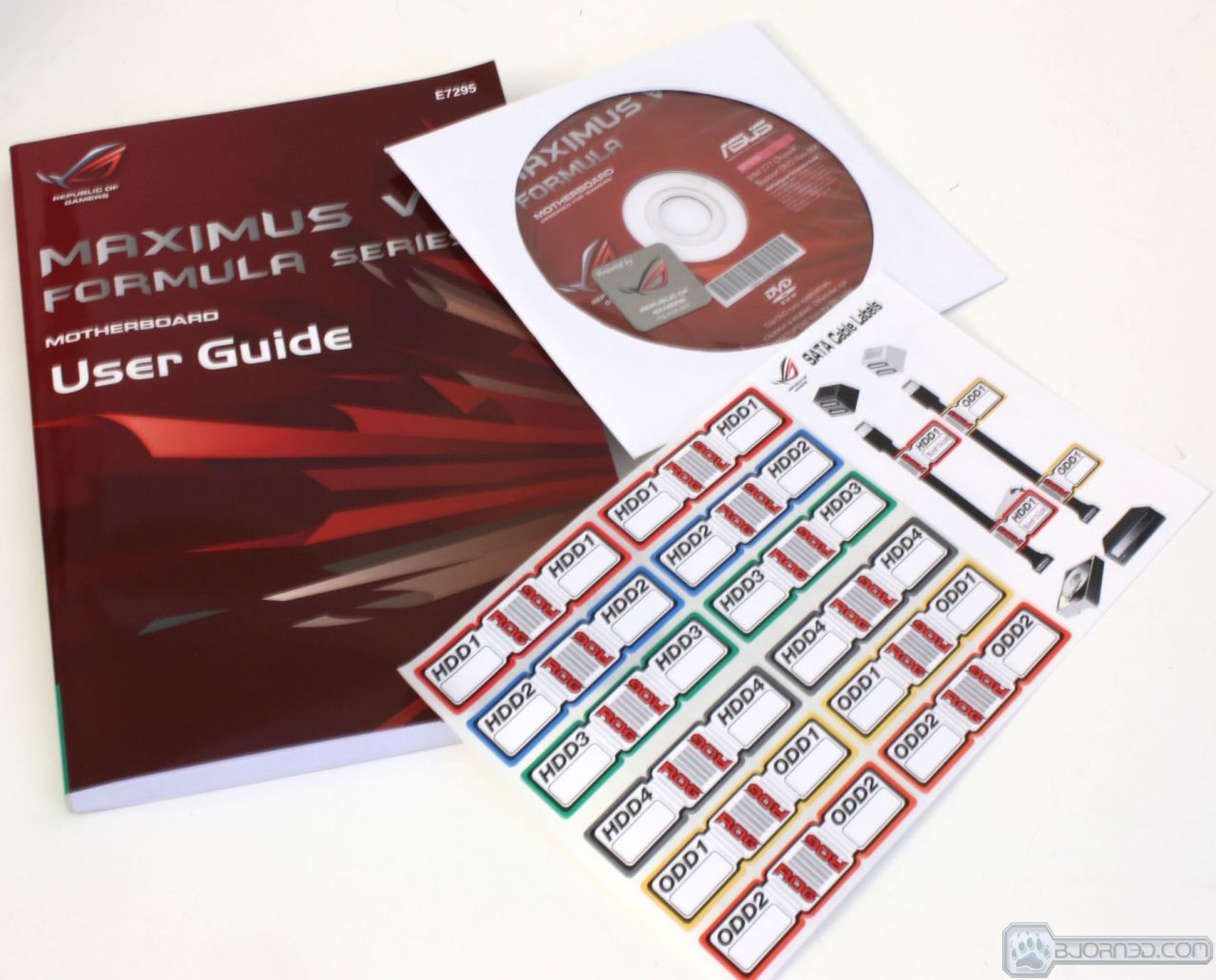
- Installation disc
- Owners Manual
The accessories are plentiful with the formula although one thing I could see as being useful would be adapters to connect the Fusion Thermo barbs to a standard 1/2″ID performance LCS tubing size. The reason we say this is that many enthusiast parts come standard as 1/2″ ID.


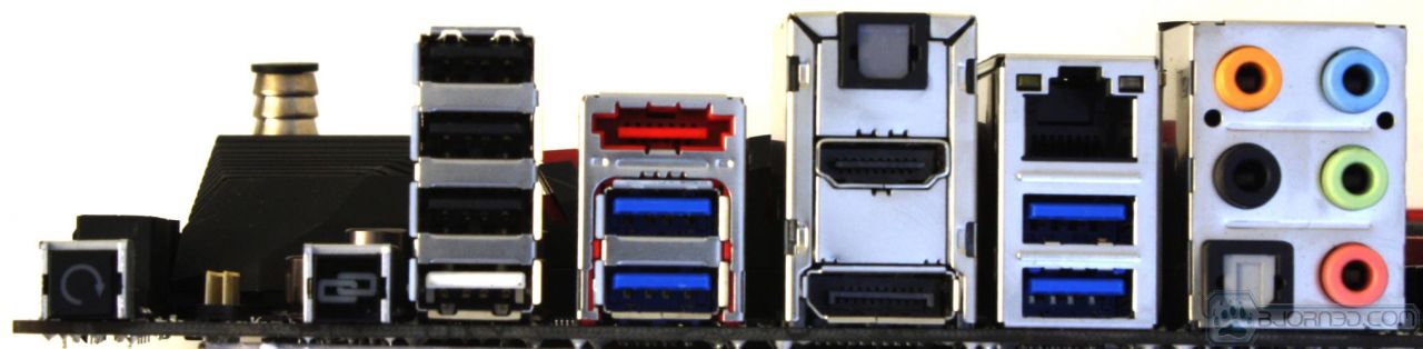
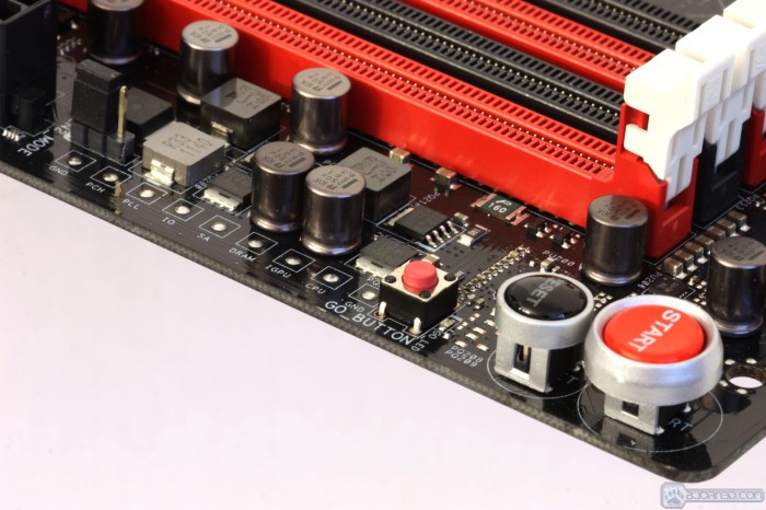
- Clear CMOS Button
- ROG Connect Button
- mSATA/mPCI-E Card Header
- 4x USB 2.0 Ports (3 Blk, 1 Wht)
- eSATA 3Gb/s Port
- 4x USB 3.0 ports (2x Asmedia, 2x Intel Z77)
- 2x Optical S/PDIF Port
- HDMI Connector
- Displayport Connector
- Intel Gigabit (10/100/1000) LAN Port
- 7.1 channel SupermeFX IV audio connections with Optical S/PDIF port
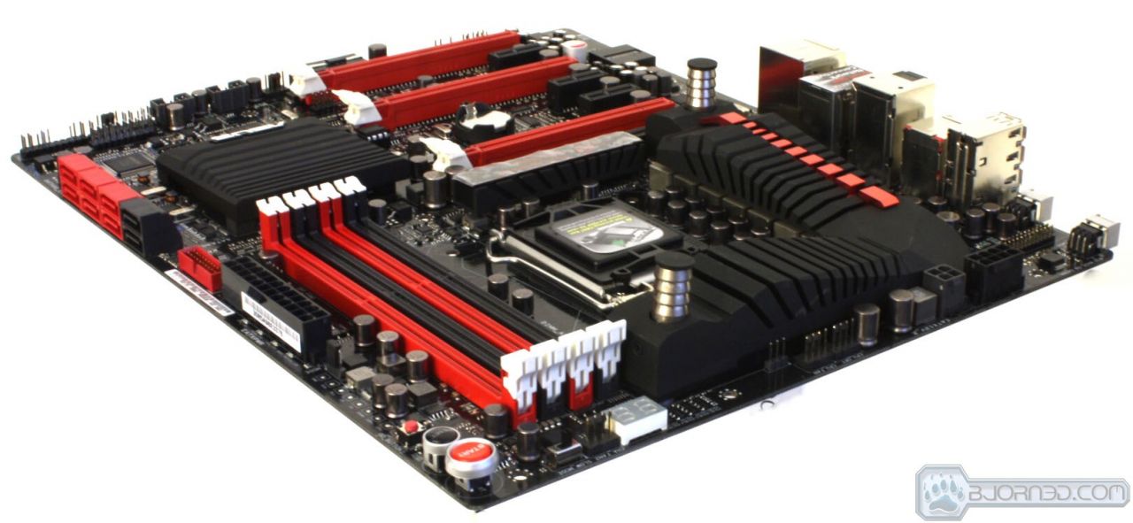
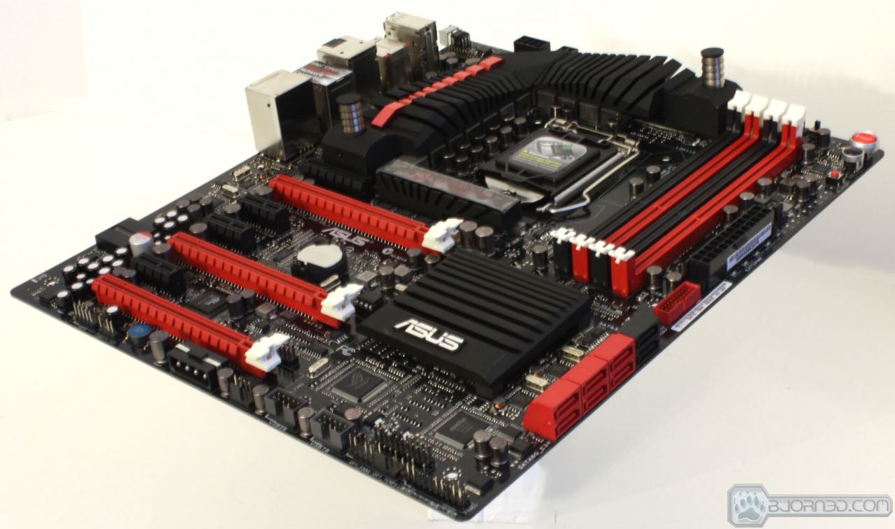
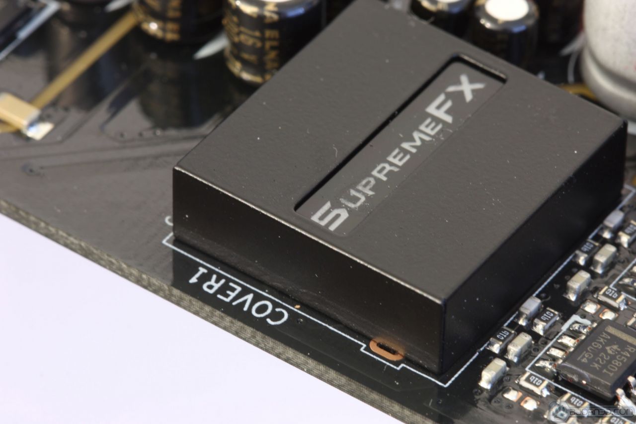
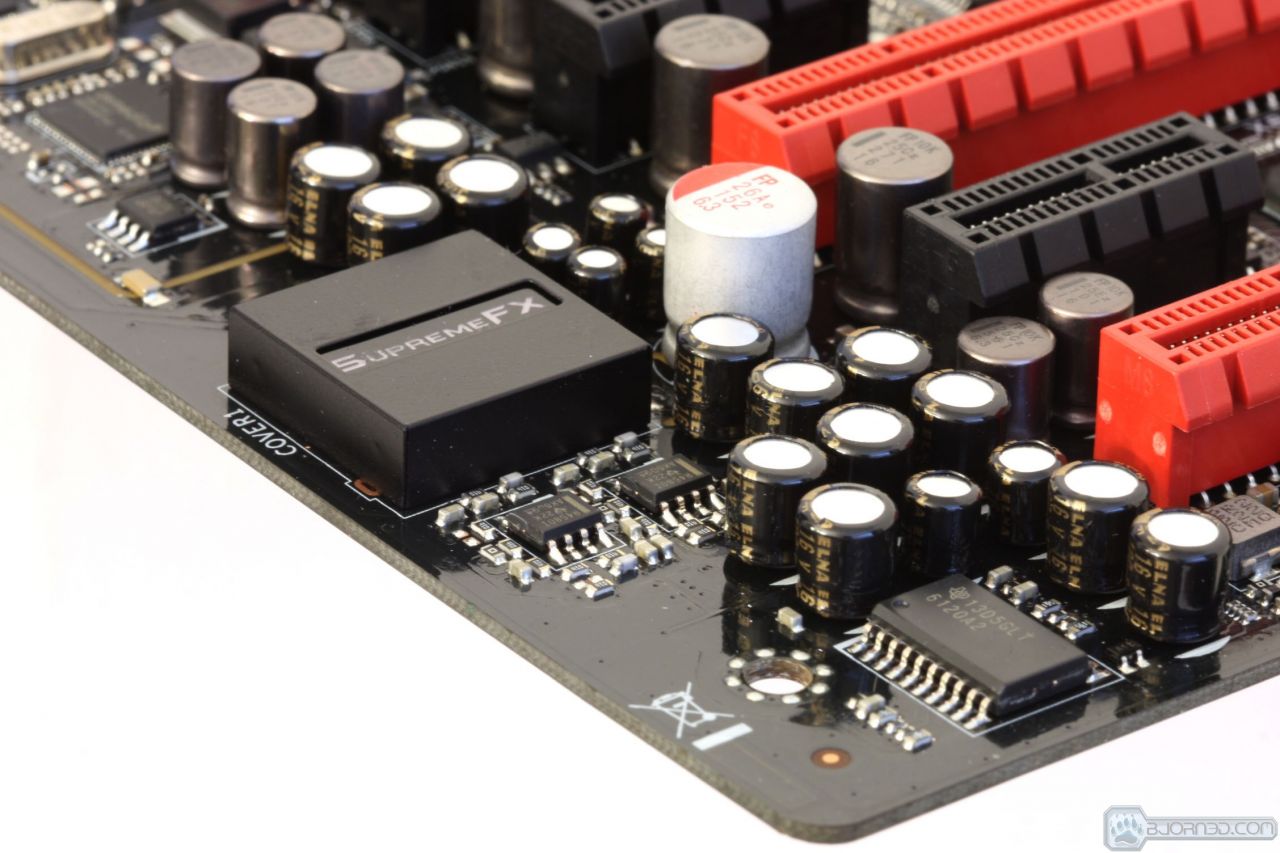
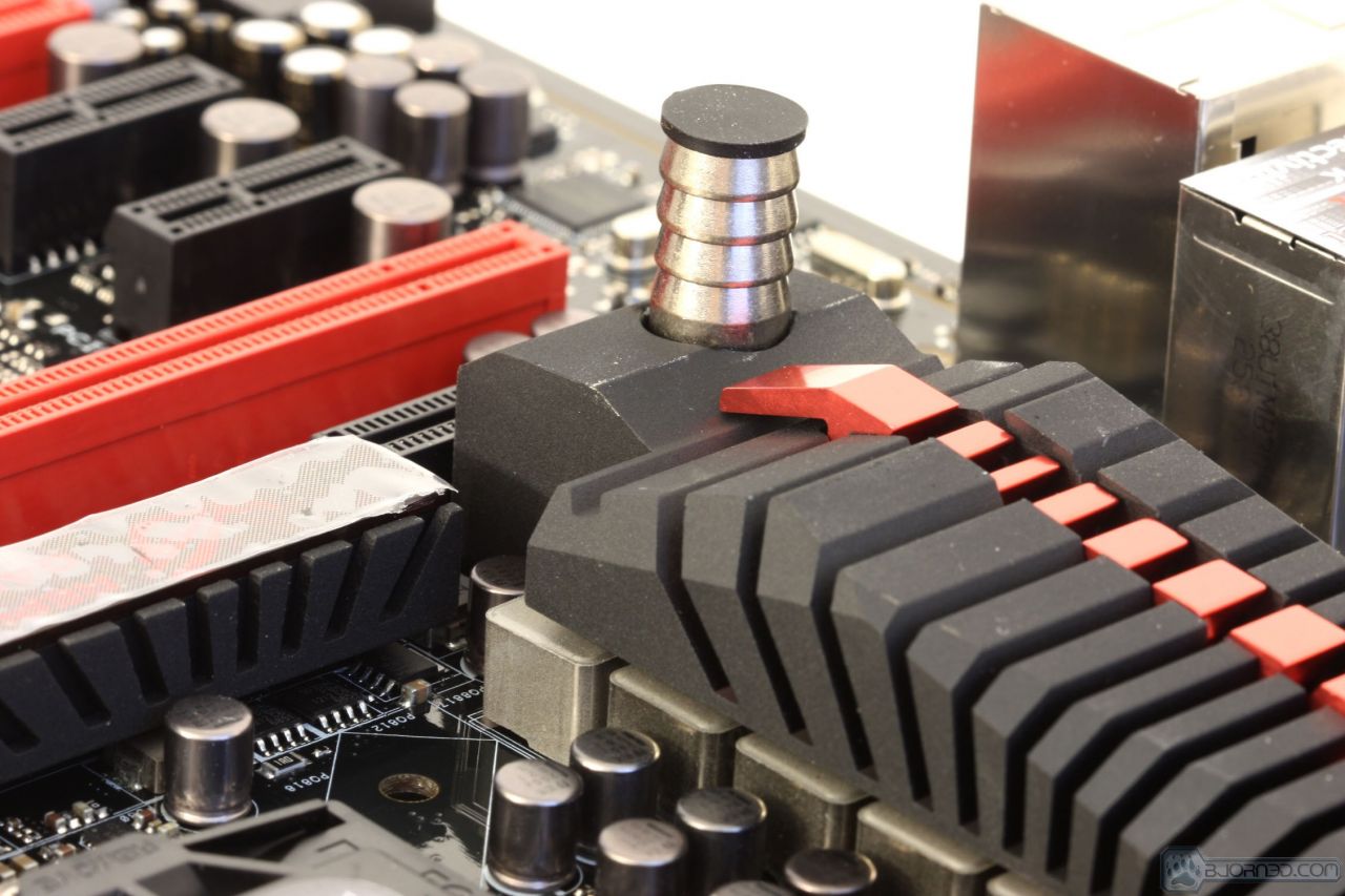
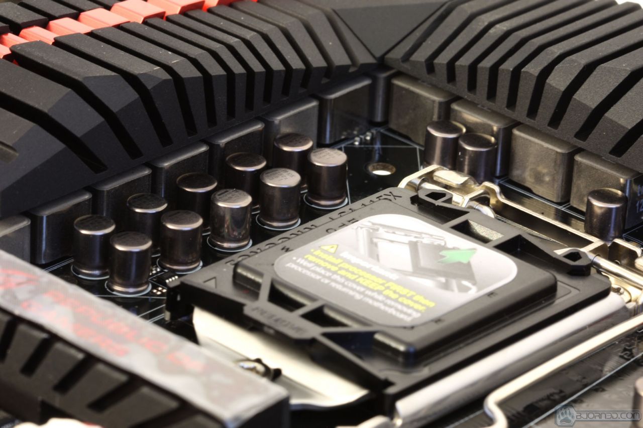
Checking out the SupremeFX IV Chipset EMI cover it is backlit red when powered on which makes for a cool look, and also the cover is functional for keeping stray signals from saturating the Analog audio signals. Also there is the large headset amplifier at the lower edge designed to ensure the audio that makes its way to your high end headset reaches there with some power behind it.
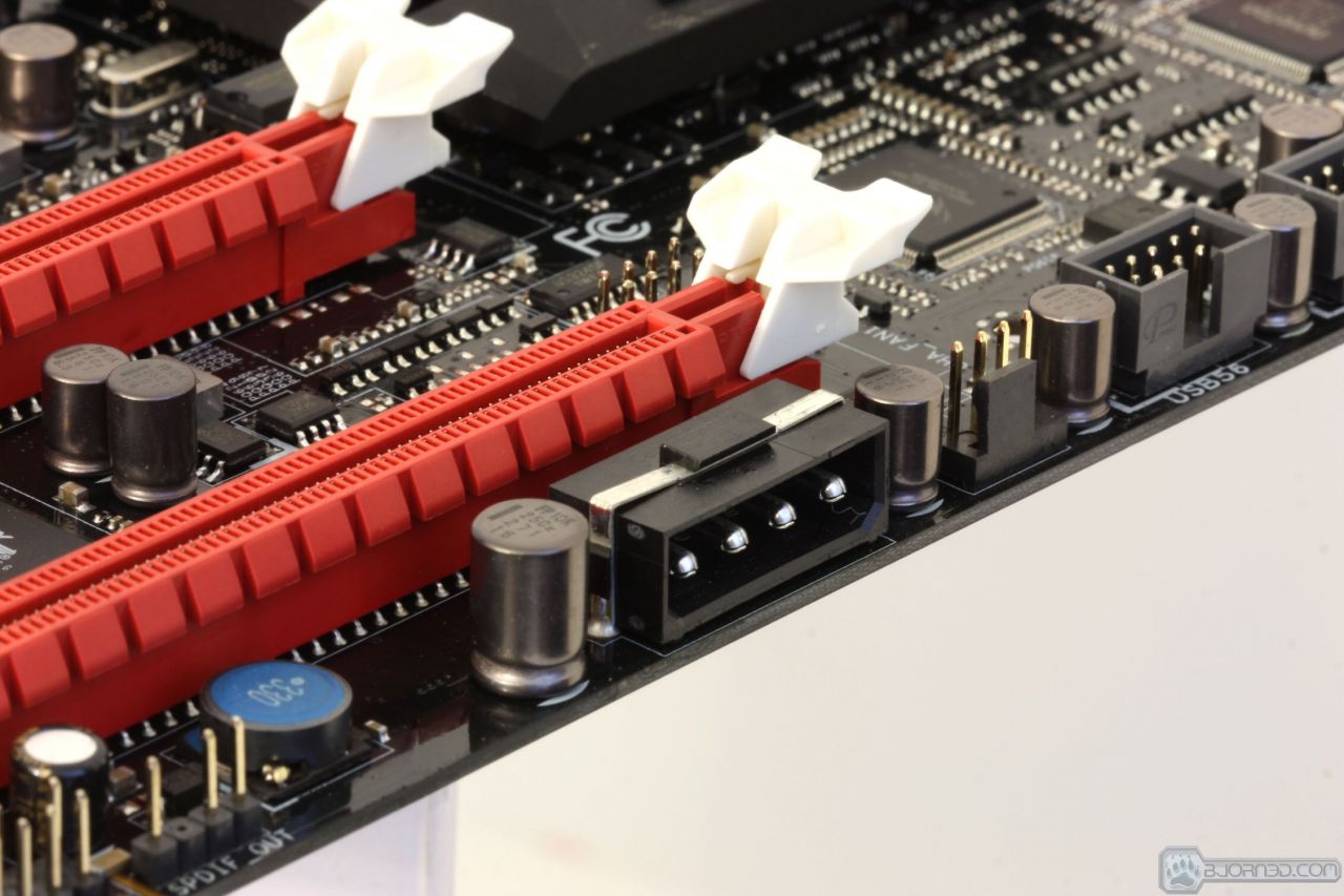
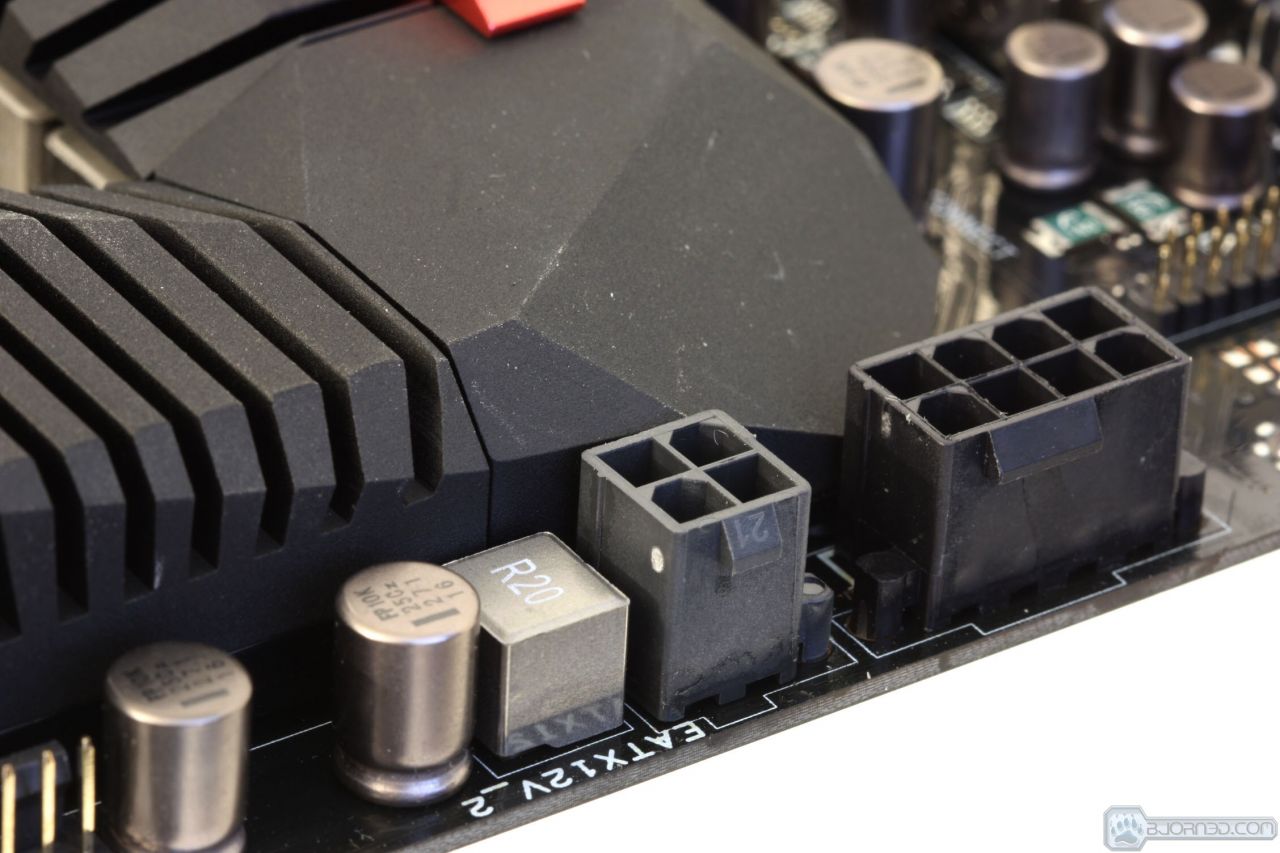
The lower edge also houses a 4 pin Molex connector which is used as supplemental power to the GPU slots to lighten load on the 24 Pin ATX connector and to ensure that there is no shortage of needed power under heavily loaded conditions.


Software Overview
AISuite

ASUS has not strayed too far from their already successful software design. However we can say that the software has been tweaked and improved while also adding new features to ensure users get the full control they expect from their board.
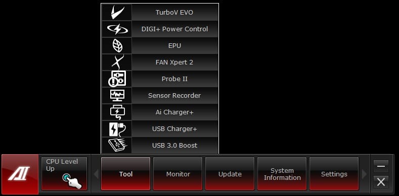
The AISuite bar has many tools and features hidden within just waiting for users to discover. We are now going to walk you through each one with some key pointers as to which does what.

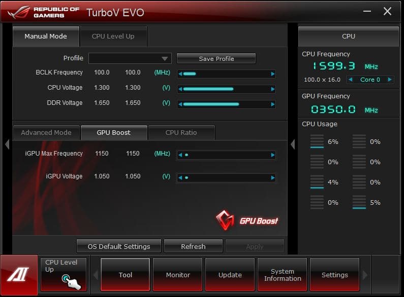
The CPU Level up button allows quick and easy single click overclocking to give a free performance boost for demanding users.
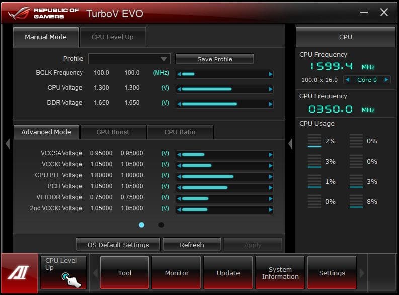
The Manual section is the polar opposite to the CPU Level Up, as it allows manual configuration of an overclock which will easily exceed the CPU Level Up presets. All of the important settings from voltages to frequencies can be adjusted here.

The DIGI+ Power Control Center has separate sections for DRAM, CPU and Smart DIGI+ power sections. Digi+ has to do with ASUS’s implementation of its industry leading digital power controls, which have been proven for excellent efficiency and accuracy which leads to better overclocking potential.
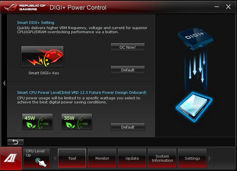
Here is what we see when entering the Smart DIGI+ power screen. For those looking for the ultimate in low power computing there is the Smart CPU Power Level which when enabled there are 2 options 45W and 35W. These settings allow limiting the CPU to these preset wattage settings for power savings and it will be throttled as such. this is especially great in business type environments where full CPU performance is never utilized as this can cut power consumption and wasted energy by quite a lot.
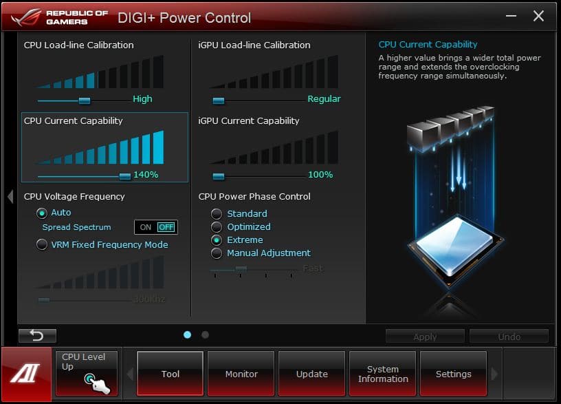
The Digi+ screen for CPU control is where we can adjust all settings related to CPU and VRM controls. This includes VRM frequencies, thermal protections and even thresholds. These are the settings you will need if pushing the limit on your chip.

The DRAM settings allow for maximum tweaking of the memory power circuits and how they behave. Much like the CPU counterparts we see this as very useful the more you push your DIMMS.
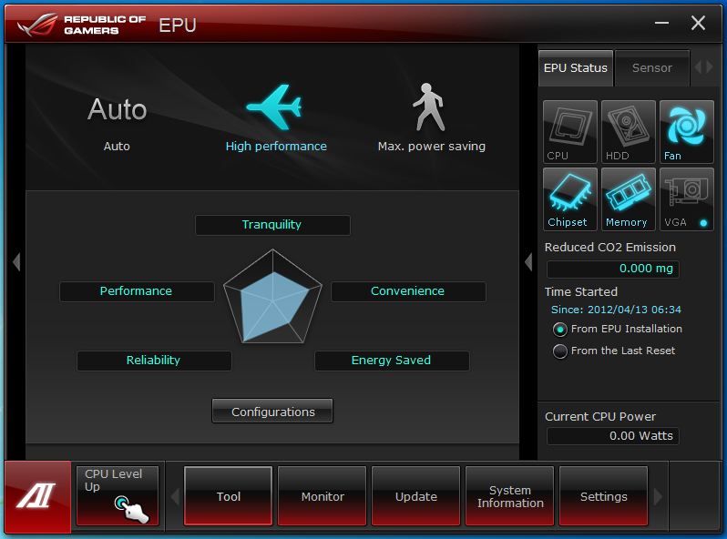
The EPU utility allows for custom tuning of the system to best match the usage model and even graphs out the present setting into whether it is more tuned toward performance and speed, or whether it is tuned toward power savings and tranquility.

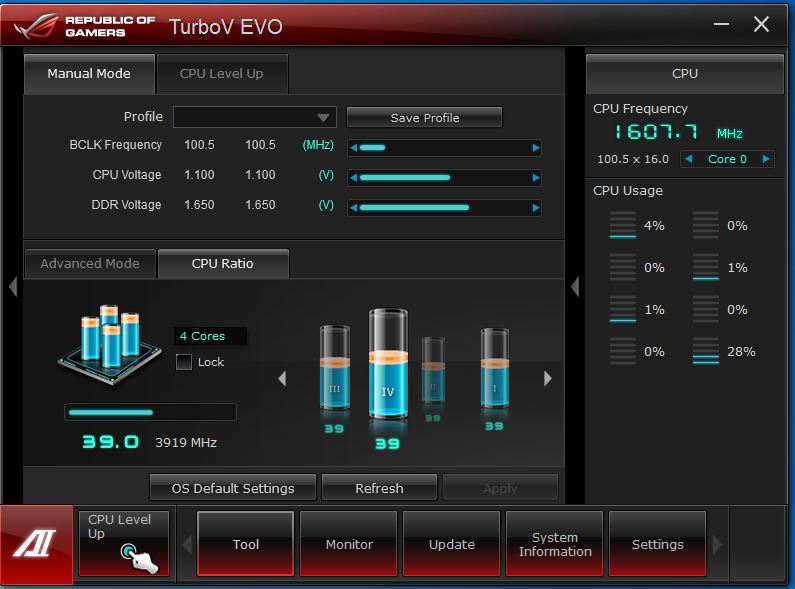
The Manual mode of the Turbo V EVO software allows for very precise fine tuning of the overclock and settings. This includes as pictured above the fact that you can adjust individual cores multiplier to allow for much better tweakability and overclock fine tuning to get the maximum performance from your rig.
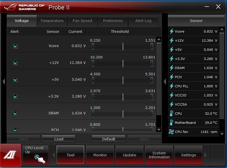
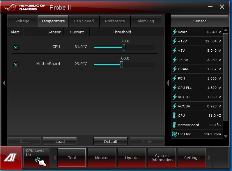

The Probe II software is very similar to what we have seen before which is simply allowing monitoring of temperatures, voltages and fan speeds all to keep a good eye on the system performance. Also here we can set alarms for specific areas we want to keep an eye on such as if a fan drops in speed below an amount we specify.
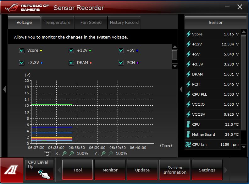
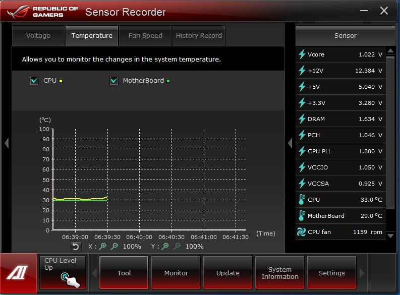
The sensor recorder function is cool because if you hear a fan ramping up during gaming or something seems to be getting to hot you can always engage the sensor recorder to monitor and graph the fan speeds, voltages or temps recorded while in game so you can better diagnose possible issues before they become bigger ones.
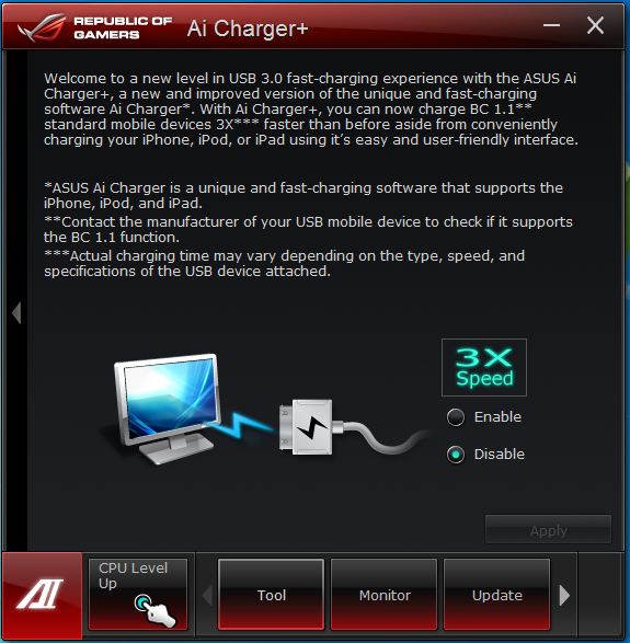
AI Charger + allows for charging of high draw APPLE i-devices at a much higher rate than before. This feature supports BC 1.1 function although as listed you will need to confirm that your device supports this spec.
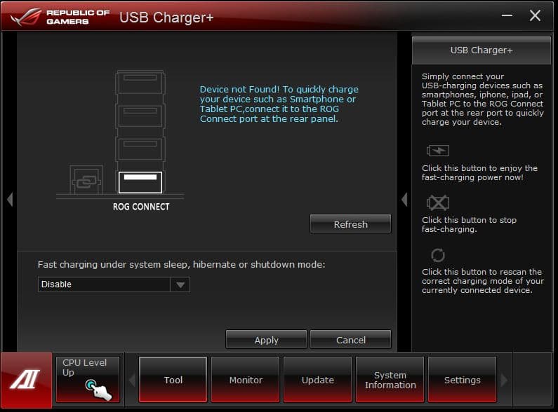
USB Charger+ is much like the AI Charger but for non i-devices or Android phones, tablets or high draw USB charged devices.
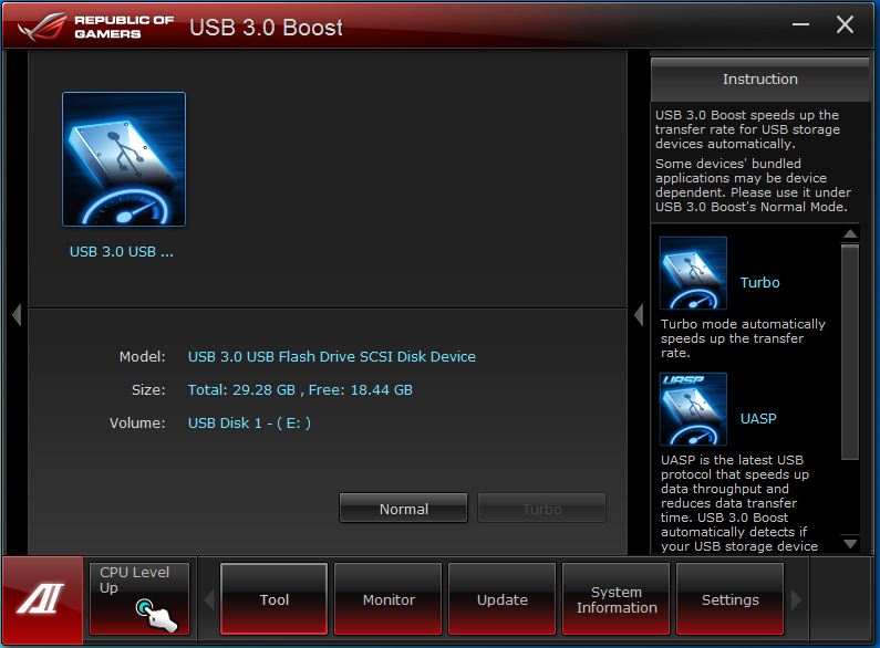
Here is the USB 3.0 boost which was covered briefly before as it allows a speed boost to many USB 2.0 storage devices and even some supported USB 3.0 storage devices by changing the communication protocol being used.
A full list of supported protocols and presently supported devices can be found here
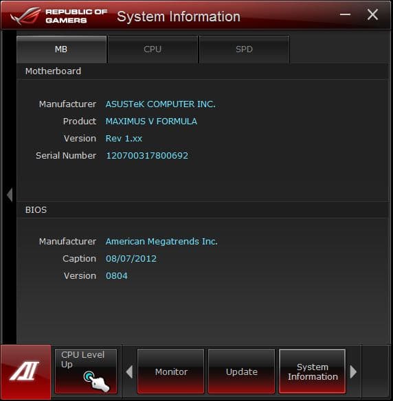
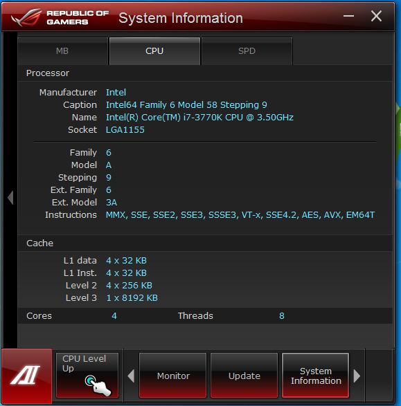
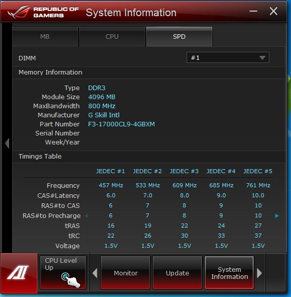
The System info screens show all of the key system specs included memory SPD info along with CPU data and also motherboard key information.
ROG Connect
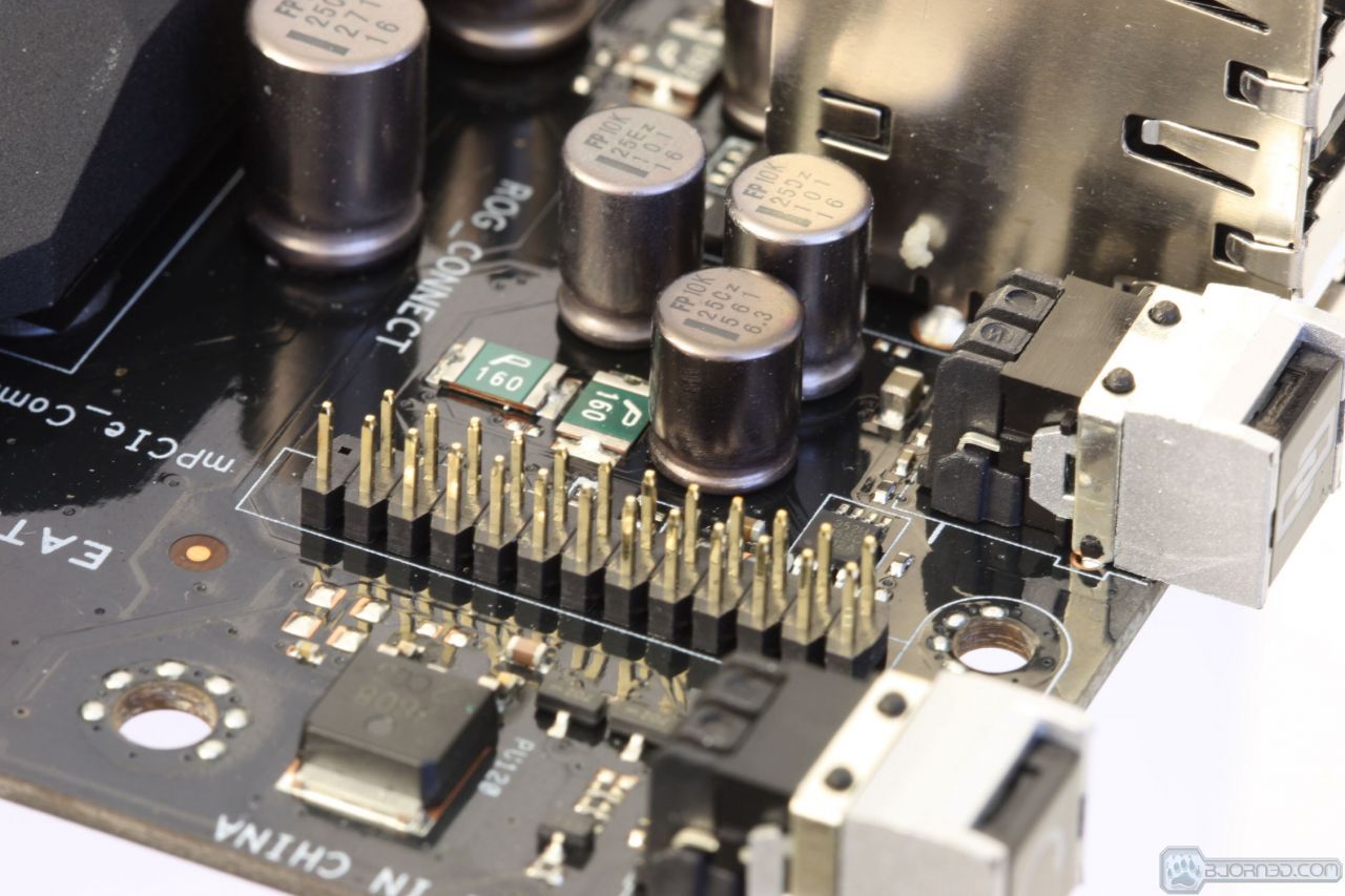
ASUS includes the ROG Connect utility with all their ROG boards. This allows connection of a remote computer via USB (with an included USB cable), which allows not only remote monitoring, but remote control of ROG boards from the separate connected system. as we see the ROG connect is the same between all of the ROG boards which is great for familiarities sake and ability to switch platforms.
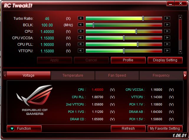
Here we have the main screen. This is RC TweakIt, which allows adjustment of all of the main voltages along with monitoring of voltages, temperatures, frequencies, and fan speeds on the remote system. This is our home screen and all menus we see from here will be accessed via this main screen to start.
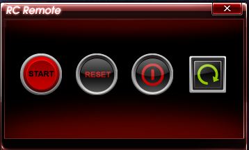
Here we have the RC Remote which allows a few key functions such as:
- Power on
- System reset
- Power Off
- Clear CMOS

This kind of message will be displayed to ensure no unintended operations or shutdowns occur because of an accidental click.

During POST, with a system connected, we see this display which tells us which point in the POST process we are at presently. This will help greatly when overclocking, in the event we suddenly run into a POST issue.

Here we have the RC diagram tool which allows remote monitoring of many sensors for fan speed, voltage/amperage, or temps to ensure our system is running well. We were very interested in the amperage of the CPU, which gives us a very good indication of the low power cycles were able to achieve during periods of idle usage.
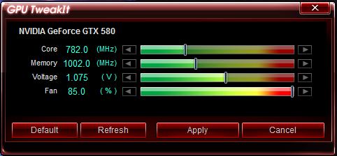
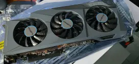
Here we see the GPU TweakIt option, which allows remote control of our ASUS GTX 580 Matrix Platinum. This program allows frequency, voltage, and fan speed changes. This could be helpful while benchmarking.
GameFirst II
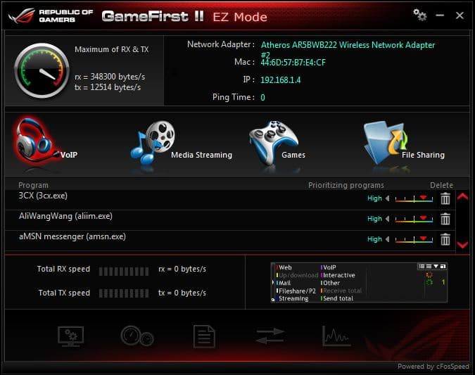
GameFirst II is yet a further improvement on the packet priority and traffic shaping controls to give you better control over your online experience. Individual programs can be tweaked for network priority to allow for full control over which programs get top spot on network access which means that downloading while gaming online is not really an issue any longer as your important game packets will get better ping and priority while the download packets can still be transferred as well.
WiFi GO!
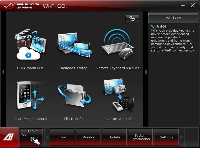
WiFi GO! is something we have looked at before but is something worth talking about. The WiFi GO! function allows for multiple different configurations to be made quickly and easily using this utility to configure multiple different usage models for the network. Things such as DLNA media streaming, remote control via tablet or other device, remote file transfers, motion control via motion enabled devices, remote desktop to compatible devices and even remote screen capture is just the tip of the iceberg as to what you can do with this.
Mem TweakIt
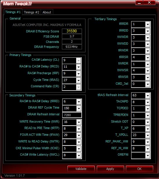
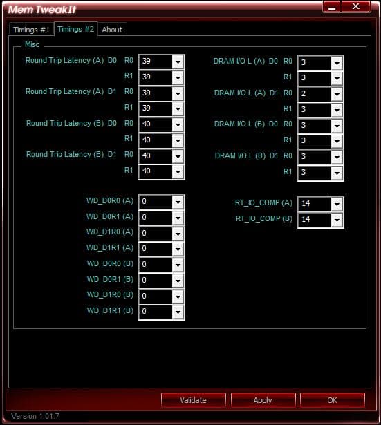
Mem TweakIt is a great program for extreme overclockers or tweakers as it allows real time adjustment and tweaking of the memory for the system which can make the difference between a high point run and a world record run.
BIOS Overview
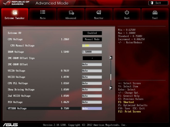
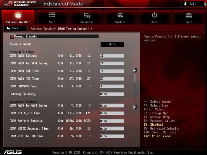
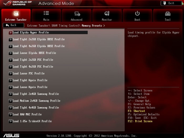
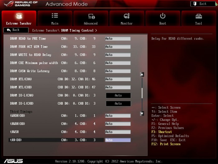
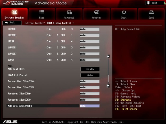
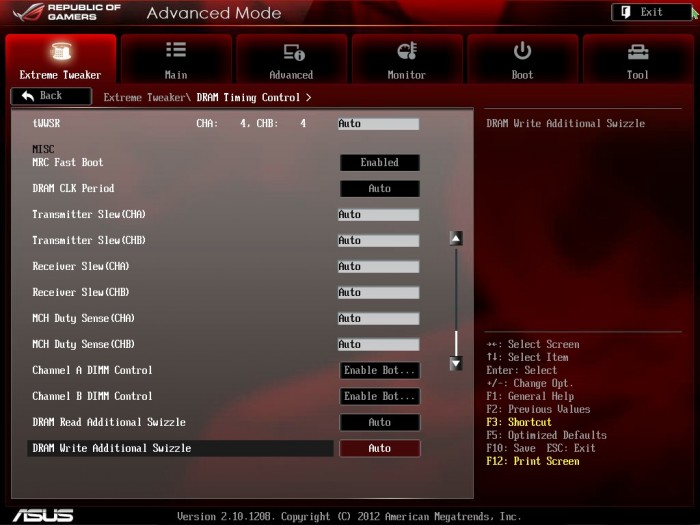
Extreme Tweaker
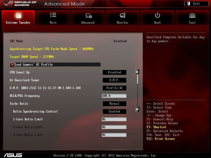

Click Image To Enlarge
This board has some of the most indepth memory clocking portions including a completely insane amount of presets depending upon the IC your memory modules use. As seen recently Ivy Bridge IMC’s tend to scale very well with PSC or older BBSE modules so if you have some of those theres a good chance you will be seeing 2200-2600 C8 or even better especially with some of the tweaking this board can do.
Click Image To Enlarge
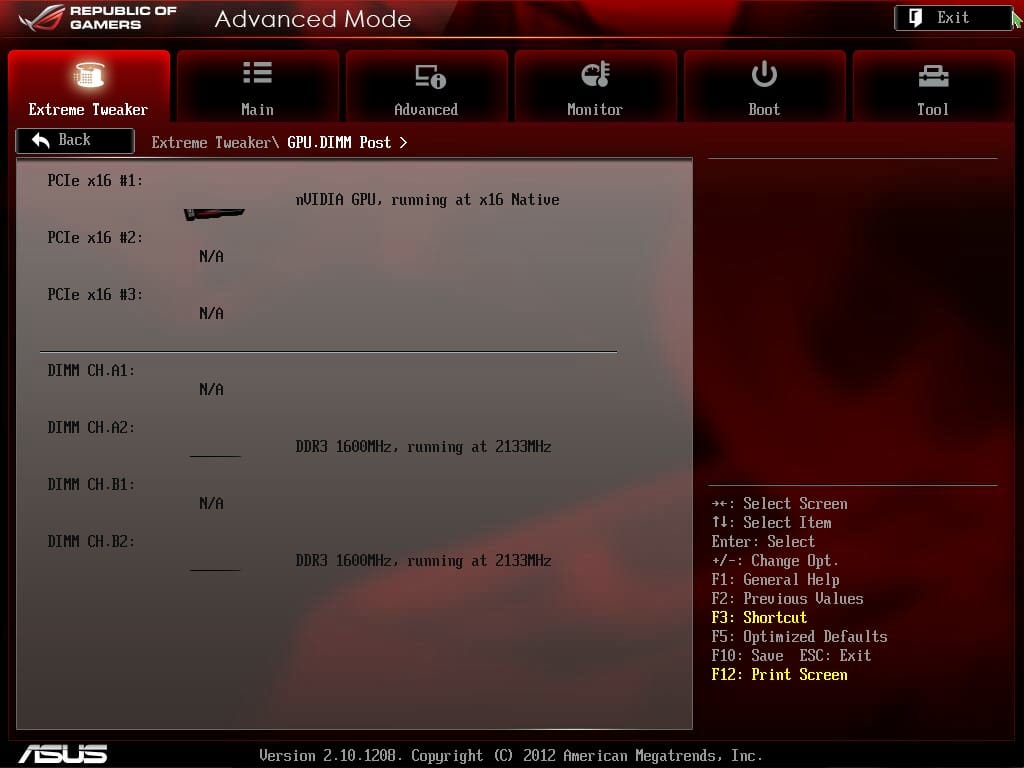
Here we have the GPU/DIMM post screen which we have talked about endlessly as to how helpful it has been previously. We had memory not showing up in the OS, this tool was extremely useful in diagnostics. None of our other methods worked, but when we entered this screen, we instantly we saw that all DIMMs were detected but one was reading as “Abnormal”, at which point we powered off and reseated that stick and all was well. This also definitely helps when running subzero and losing a memory stick detection (turned out a little too much vaseline in the DIMM slot cause it not to make adequate contact)

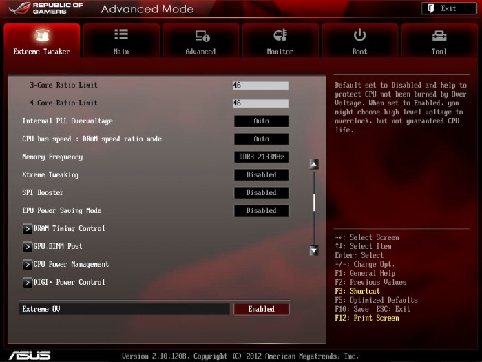
Click Image To Enlarge
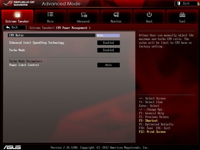
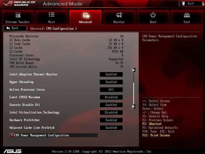
Here we have the CPU power management screen which deals with a few key processor technologies. This area allows for enable/disable of speedstep, turbo and of course adjustment of the CPU ratio and the turbo power limit control.
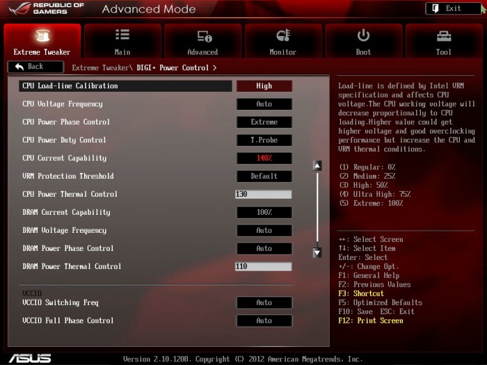
Also the Digi+ screen is another important one as it can really open up the throttle on your overclocking efforts by extending power limits well beyond stock values where otherwise the limits would stop you from seeing the platforms full potential. Thsi is also where you can adjust the performance of each of the Digital PWM components that are found in the Digi+ implementation. Once again here setting extreme values while it may allow more overclocking headroom do keep in mind that you are opening the door to more thermal dump and higher temps so be sure not to just crank everything up for no reason unless your going cold.


Click Image To Enlarge
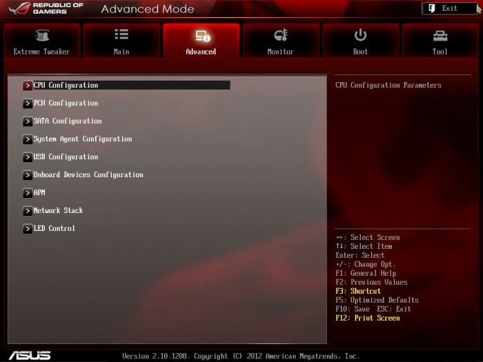
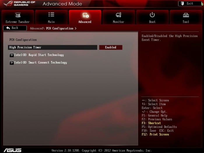
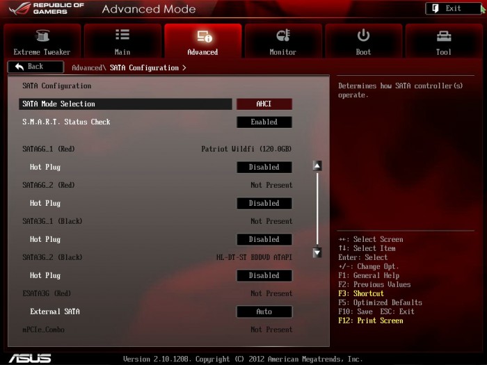
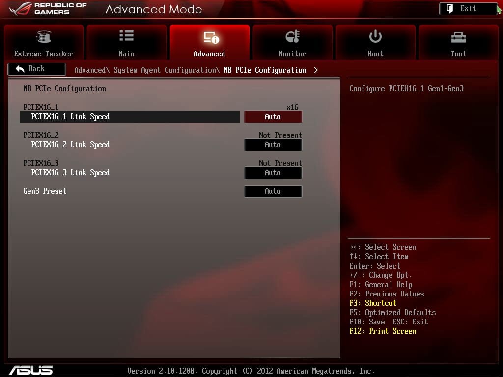
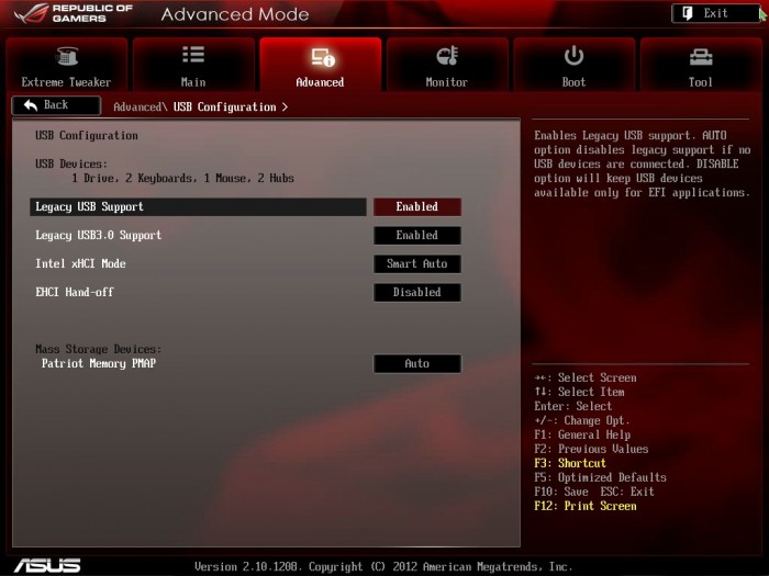
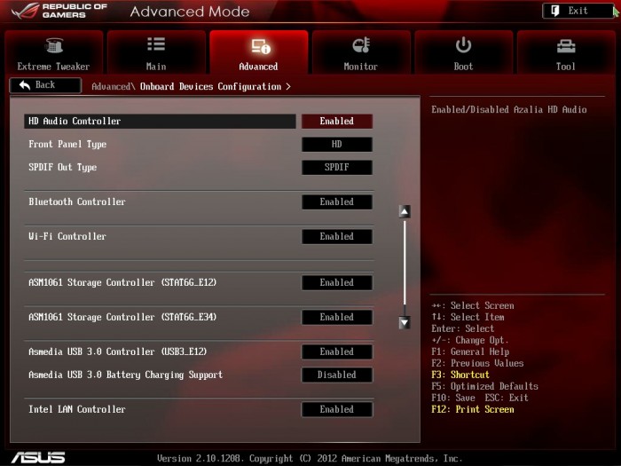
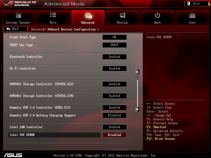
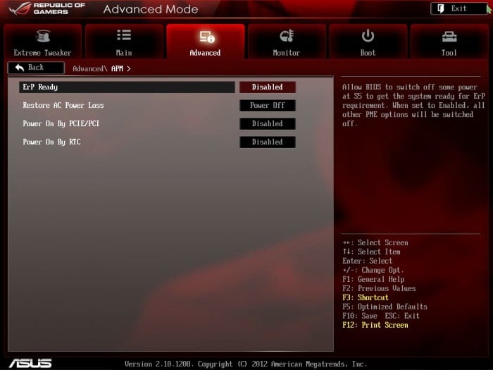
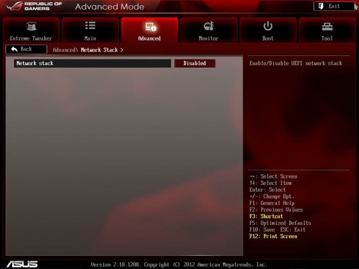
Here we have some of the advanced board features including many settings such as CPU feature settings. Also seen in this area will be SATA settings and many others to adjust how the components operate on the board. This is all fairly standard stuff you will see on most boards so we put up a few shots just to show the general more important options and their layout.
Click Image To Enlarge
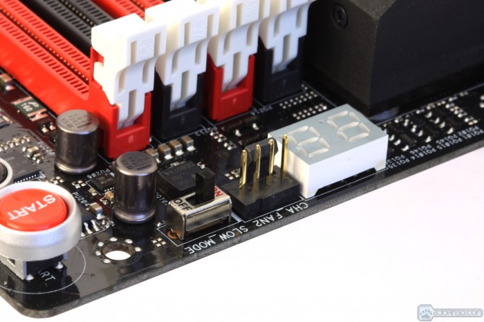
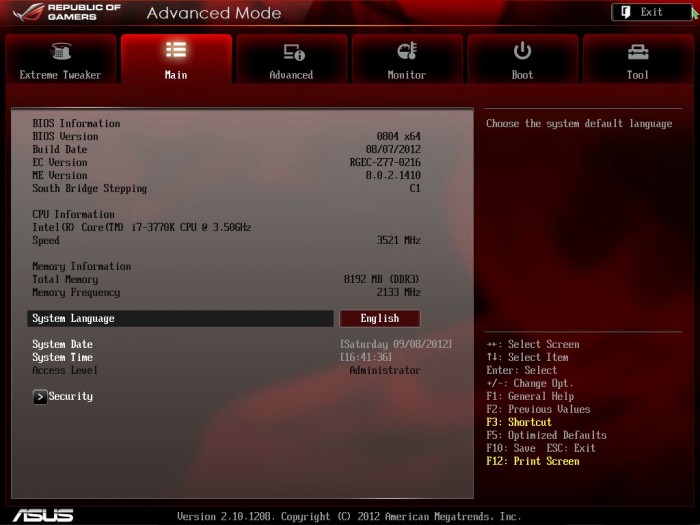
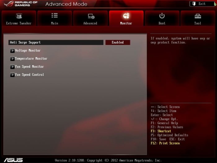
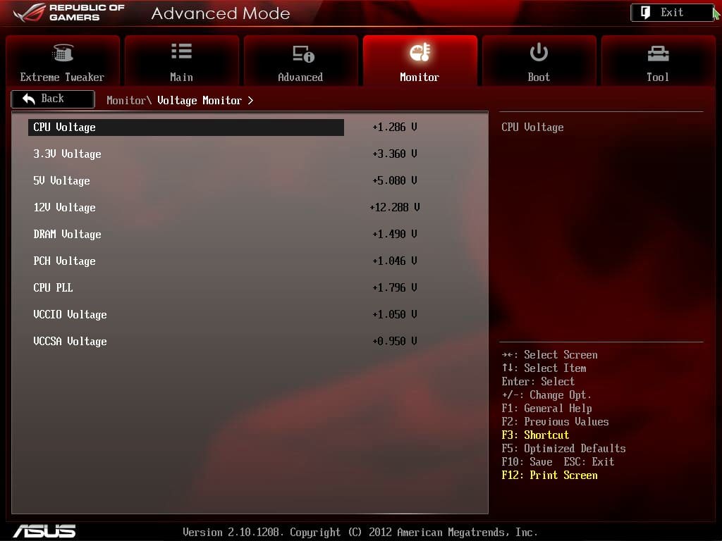
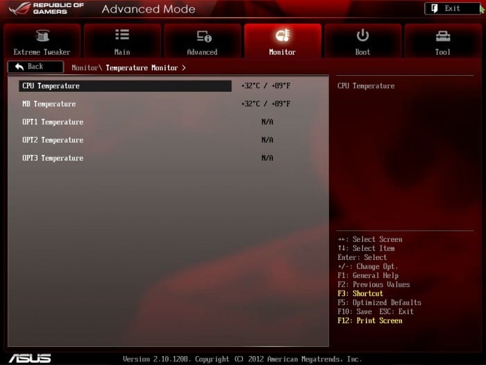
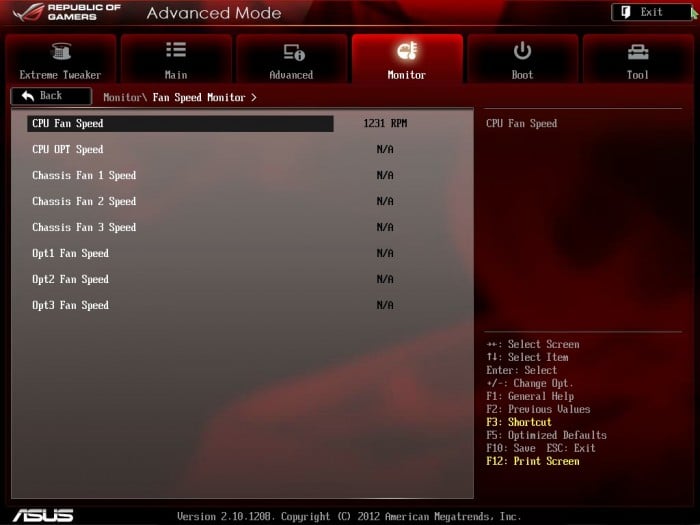
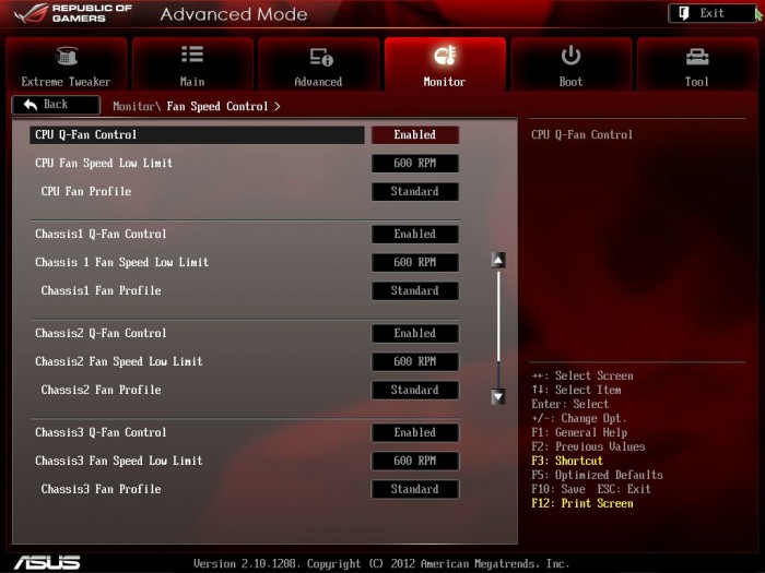
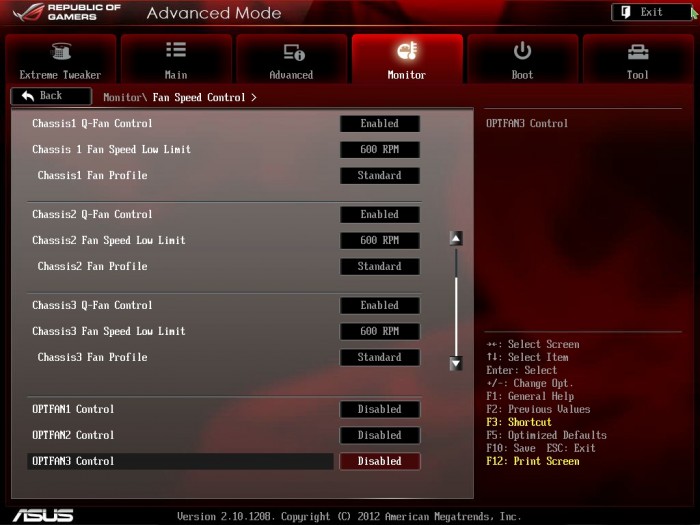
The monitoring area allows for multiple options from monitoring voltage, to temperatures and even fan speeds. With the inclusion of the Fan Xpert II Software the cooling fan performance is now at a whole new level so adjusting in the BIOS will be a thing of the past.

Click Image To Enlarge
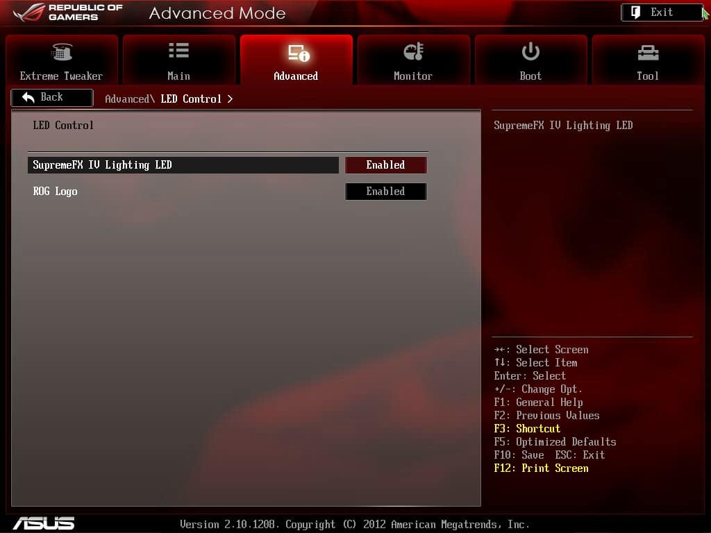
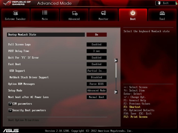
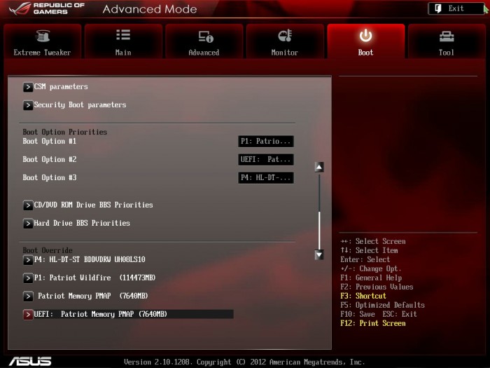
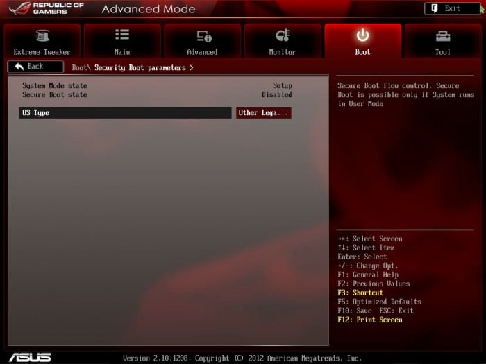
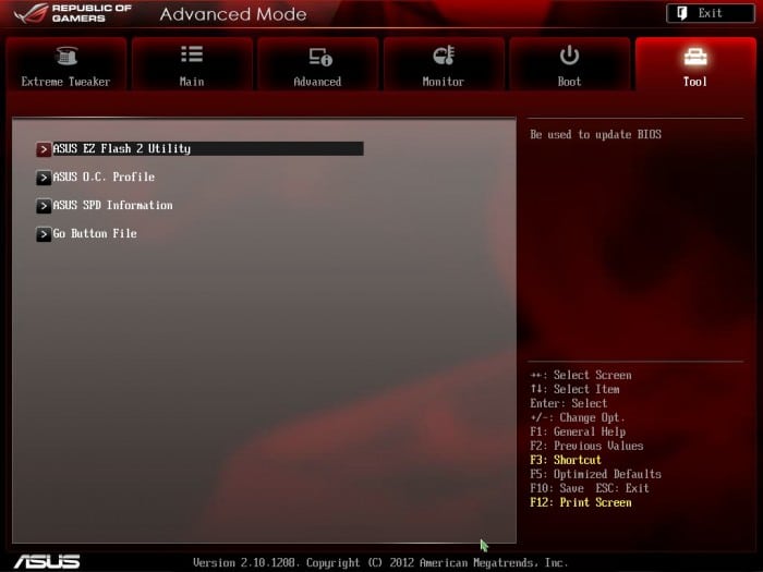
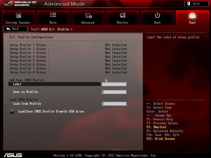
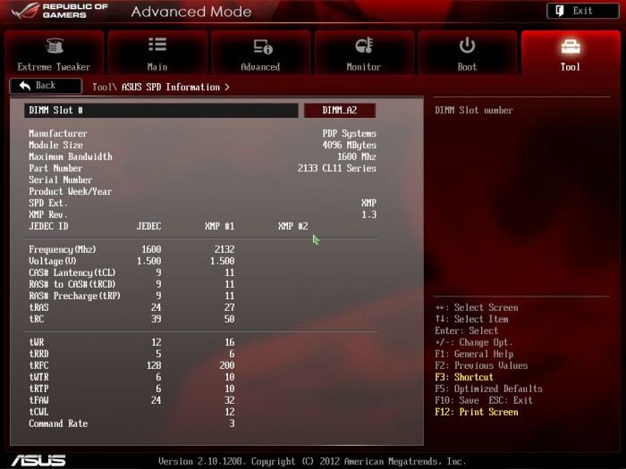
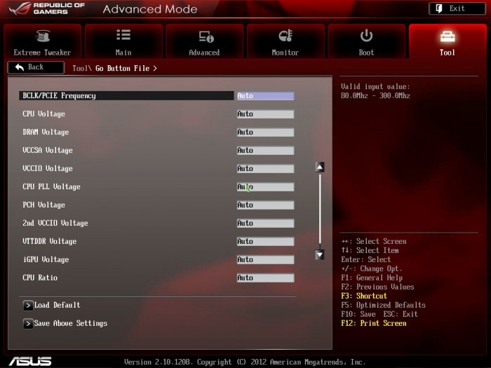
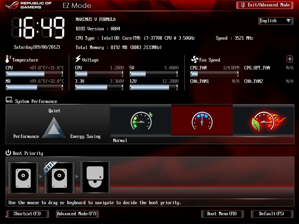
The rest of the settings are just basic boot setup and BIOS flashing tools which all are standard fare for motherboards. Lastly we have the tools which of course include the EZ Flash 2 utility, memory SPD reader and even clock profiles to allow you to save your favorite overclock settings. And lastly the EZmode bios which is a primarily GUI interface where a few clicks easily can do some basic setup in the UEFI.


I wanted to get a Maximus series ROG board but they just coast too much 350+ at the time. I decided to go with a cheaper priced board. I like the marketing spin for the red line.