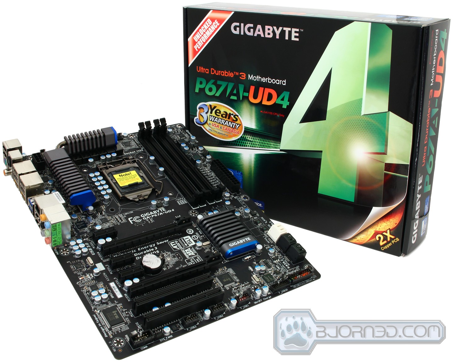
The GIGAYBTE P67A-UD4 motherboard is designed with mid- to high-end users in mind, providing enough performance and features that an average user would want in a motherboard.
Introduction – GIGABYTE P67A-UD4
Overview
With the release of the new 32nm Intel Sandy Bridge processors, including the Core i3, i5 and i7, many users are interested in finding out more about the new P67 Express Chipset motherboards, which can push the latest K series processors to unbeliveable frequencies. The GIGABYTE GA-P67A-UD7 motherboard we just reviewed was designed for Extreme Gamers, Film and Video Editors and Overclocking Enthusiasts, providing the users with features that only a smaller percentage of users actually need, though the ones that do are sure to appreciate them. In this review, we’ll take a look at the GIGABYTE GA-P67A-UD4 motherboard, which is more suitable for enthusiast users who don’t want to push their hardware to stratospheric levels.
While the UD7 will be the most reliable and stable motherboard of GIGABYTE’s P67 lineup, the GA-P67A-UD4 will fit perfectly for those looking at upgrading their older Core 2 Duo, Core 2 Quad or even recent Nehalem-based i3, i5, and i7 processors. It will also be a good board for users transitioning from AMD based motherboards. The P67A-UD4 motherboard offers plenty of features that enthusiasts and gamers are looking for, like USB 3.0, SATA III, SLI and CrossFire X support, as well as excellent high-quality PCB and component design with overclocking features that will make applications fly using the latest Core i5 and i7 LGA1155 socket Sandy Bridge processors. The Sandy Bridge K-series processors combined with high end P67 motherboards like the GIGABYTE P67A-UD4 provide excellent overclocking features while maintaining a low power consumption and low temeprature output.
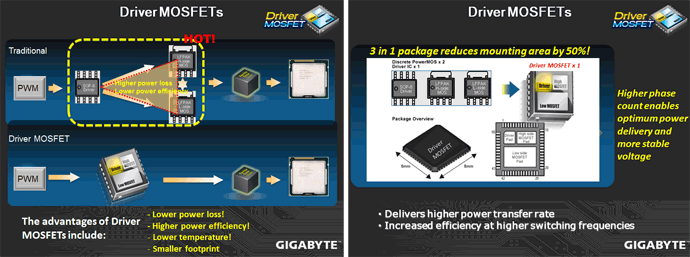
GIGABYTE still continues to include the same features that brought their products such acclaim, like the Ultra Durable 3 design, ON/OFF Charge and 333 Onboard Acceleration. With the new P67 Chipset Motherboards, GIGABYTE has also upgraded their VRM design by using Driver MOSFET packages over regular MOSFETs. These Driver MOSFETs deliver higher power transfer rate and increase efficiency at higher switching frequencies. The Driver MOSFET’s also provide lower power loss, lower temperatures, and a smaller footprint over regular MOSFETs
Current Intel chipsets support PCI-Express 2.0 at a lower 2.5GT/s, which limits each direction of a lane to a maximum of 250MB/s. With USB 3.0 and 6Gbps SATA interfaces connected to PCI-Express x1 slots, devices connected to these interfaces will be limited to the 250MB/s speeds. A nice change on the P67 lineup of motherboards allow the PCI-Express slots to operate at a stunning 5GT/s, providing up to 500MB/s of bandwidth in each direction. This adds up to 1GB/s bidirectional bandwidth.
Another very nice improvement on the P67 Express Chipset with the proper BIOS allows users to take advantage of 3TB hard drives in their systems, as opposed to the 2TB-2.2TB limitation from X58 based motherboards. The GIGABYTE P67A-UD4 motherboard updated to the latest BIOS supports 3TB hard drives.
Also, some manufacturers like ASUS are slowly making the move to the UEFI (Unified Extensible Firmware Interface) BIOS instead of the traditional 32-bit BIOS on their P67 motherboards. The UEFI provides a GUI (Graphical User Interface) for the BIOS, making it possible to not only use the keyboard, but also the mouse to adjust system settings. This is also easier on the eyes, especially for users not used to the DOS like systems. Unfortunately, at the moment GIGABYTE does not offer support for UEFI.
The P67A-UD4 has full overclocking potential when paired with the appropriate unlocked K-Series processor, including an unlocked memory multiplier. The H67 architecture motherboards unfortunately have a locked memory multiplier, but can take advantage of Intel’s integrated graphics that are built into all Sandy Bridge CPUs, whereas the P67 boards cannot. This is why there are several video outputs on the H67 lineup of motherboards and none on the P67. Right now it seems that there will not be a hybrid solution for the Intel Sandy Bridge built-in GPU to work together with dedicated video cards, but this is not definite and could change in the future.
The GIGABYTE P67A-UD4 will be running for an affordable MSRP of $199.99, not the $239.99 MSRP that we first expected. While it is not the cheapest motherboard on the market, it sounds like a fair price for its features and quality.
Thank you for AcousticPC.com for providing us with a quiet, jet powerful water cooling setup to test out the overclocking portion of the board.
Special Features
- 12 phase power design for excellent power delivery.
- GIGABYTE Ultra Durable™ 3 design with 2x Copper PCB to provide the stability, reliability and longevity essential to meet the power needs of high-end processors and other components running today’s most demanding applications and games.
- Onboard 2 SuperSpeed USB 3.0 ports (up to a total of 4 USB 3.0 ports) and 2 SATA 6Gbps (internal) and 2 SATA 6Gbps (external) to deliver impeccable data transfer speeds.
- CrossFireX™ and Nvidia® SLI™ support for great gaming experience.
- New Matte Black color PCB offering a stylish new outlook that blends itself to decoration and case mods.
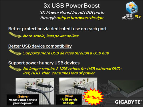
- Unique GIGABYTE 3x USB Power design with On/Off Charge USB ports to offer faster battery charging for iPhone, iPad and iPod devices.
- GIGABYTE patented DualBIOS™ technology delivering the highest level of failure protection.
The P67A-UD7 motherboard was engineered for users that want to get the most out of their hardware, whether they have a 3-way SLI setup or want to use several USB 3.0 and SATA III devices, or even need Dual Gigabit LAN support. Unfortunately, the P67A-UD4 does not support Dual Gigabit LAN or 3-Way SLI, but it does give the users partial USB 3.0 and SATA III support. On the UD7 there are 10 USB 3.0 ports at the rear end of the motherboard and up to 8 internal ports, while on the UD4 there are only 2 rear ones and 2 internal. However, unless the case being used already has USB 3.0 ports prepared, the front panel USB 3.0 device is not included with the motherboard, and needs to be bought separately. Also, instead of 6 SATA III ports, the user can utilize up to 2 SATA III ports inside the case. There are 2 more eSATA III ports available at the rear end of the motherboard where the I/O connectors are located.
There are also several features missing from this motherboard that an overclocker would enjoy, but this is not a deal breaker. The GA-P67A-UD4 is missing some of the basic test bench features, like the on/off switch and the reset switch. Users will actually need a case to run this motherboard. Also, while this motherboard comes with PHASE LEDs, it does not come with temperature LEDs, or even voltage LEDs. This motherboard also does not have a clera CMOS button or something similar to that.
The VRD12 Design and the Driver MOSFETs add a bit more to the P67A lineup of motherboards by having something not seen on previous GIGABYTE motherboards. The implementation of the 12 phase power, the VRD12 and Ultra Durable 3 design, along with the new driver MOSFETs, are mainly there for extreme overclockers and gamers or for cool and power efficient operation for general average users.


GIGABYTE 6 series motherboards incorporate an Intel® approved Intersil PWM controller that is VRD 12 (Voltage Regulator Down) compliant. This means that it offers new features that include SerialVID (SVID) which transfers power management information between the processor and voltage regulator controller, allowing more robust and efficient signaling control between the CPU and PWM controller – hence, delivering a more energy efficient platform.

A traditional Voltage Regulator Module (VRM) consists of a Choke, Capacitors, MOSFETs and a Driver IC. By incorporating the MOSFETs and driver IC in accordance with the Intel® Driver-MOSFET specification, we can achieve higher power transfer and increased efficiency at higher switching frequencies to satisfy the growing power requirements of today’s processors. Driver-MOSFETs also help to reduce VRM real estate requirements in the CPU zone.


Driver MOSFETs are completely redesigned MOSFETs combining the driver pad, the High side MOSFET pad and the Low side MOSFET pad into one component. This helps reduce mounting area by up to 50%. The Driver MOSFETs are capable of achieving lower working temperatures, higher power efficiency, and lower power loss, making current transfer much faster and smoother while still maintaining stable voltage under heavy load.


GIGABYTE DualBIOS™ is a patented technology that automatically recovers BIOS data when the main BIOS has crashed or failed. Featuring 2 physical BIOS ROMs integrated onboard, GIGABYTE DualBIOS™ allows quick and seamless recovery from BIOS damage or failure due to viruses or improper BIOS updating. In addition, GIGABYTE DualBIOS™ now supports booting from 3TB+ (terabytes) hard drives without the need for partitioning, and enables more data storage on a single hard drive.


The GIGABYTE Ultra Durable™ 3 design features twice the copper for both the power and ground layers of the PCB, dramatically lowering system temperature by efficiently spreading heat from critical areas of the motherboard (such as the CPU power zone) throughout the entire PCB. GIGABYTE’s Ultra Durable™ 3 also lowers the PCB impedance by 50%, which helps to reduce electrical waste and further lowers component temperatures. A 2x Copper layer design also provides improved signal quality and lower EMI (Electromagnetic Interference), providing better system stability and allowing for greater margins for overclocking…more

Note: Due to certain mobile phone limitations, users may need to connect the mobile phone to their PC before the PC enters S4/S5 mode to enable a quick charge from non On/Off Charge USB ports. Charging results may vary by model.


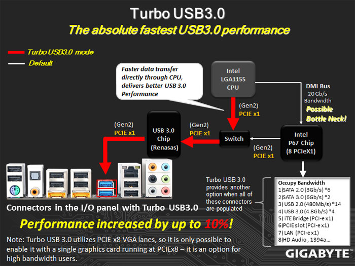
When GIGABYTE’s Turbo USB3.0 feature is enabled, it provides the fastest possible USB3.0 performance by allocating PCIe lanes to directly connect the CPU and USB 3.0 controller chip. This provides approximately 10% better performance than when it is disabled and USB 3.0 traffic is directed through the chipset.
Note: Turbo USB 3.0 utilizes 8 PCIe VGA lanes, so it is only possible to enable it with a single graphics card running at PCIe x8 on P67 chipset motherboards, or while using Intel® HD Graphics from the CPU (i.e. no VGA card) on H67 chipset motherboards. It is an option for high bandwidth users.


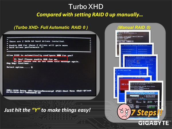
Turbo XHD function only enabled for the SATA controllers integrated in the Intel P67/H67 Chipset.


Featuring with two external SATA (Power eSATA) ports in the rear panel that provide smart setup and hot-plug functionality that allows easier data backup and content manipulation on external storage devices.


Dolby Home Theater® places listeners in the middle of the action, giving their PCs a powerful set of tools to deliver a cinema-style experience in vivid surround sound.
- Delivers vivid surround sound for music, movies, and games, using two to eight speakers or any set of headphones
- Designed to automatically deliver the best possible listening experience

Specifications
The P67A-UD4 is slightly different from the UD7. As mentioned before, the UD7 had a Dual Gigabit LAN whereas the UD4 only has a single LAN connector controlled by the Realtek 8111E controller. The way the UD7 is able to fit two LAN connectors is by running two Realtek 8111E controllers onboard.
| Specification | GIGABYTE P67A-UD4 |
|---|---|
| CPU | Supports 2nd Generation Intel® Core™ processors in the LGA1155 package |
| Chipset | Intel® P67 Express Chipset |
| Memory |
(Go to GIGABYTE’s website for the latest supported memory speeds and memory modules.) |
| Audio |
|
| LAN | 1 x Realtek RTL8111E chip (10/100/1000 Mbit) |
| Audio |
8-Channel Audio |
| Expansion Slots |
|
| Multi-Graphics Technology | Support for ATI CrossFireX™/NVIDIA SLI technology * The PCIEX16 slot operates at up to x8 mode when ATI CrossFireX™ is enabled. |
| Storage Interface | Chipset:
Marvell 88SE9128 chip:
|
| USB | Chipset:
2 x Renesas D720200 chips:
|
| Internal I/O Connectors |
|
| Back Panel Connectors |
|
| I/O Controller | iTE IT8728 chip |
| H/W Monitoring |
|
| BIOS |
|
| Unique Features |
|
| Bundle Software | Norton Internet Security (OEM version) |
| Operating System | Support for Microsoft® Windows® 7/Vista/XP |
| Form Factor | ATX Form Factor; 30.5cm x 24.4cm |
| Notes |
|
Software Overview

Here are some great applications that GIGABYTE includes with the P67A-UD4 motherboard. Most of these applications also come with other model motherboards, including the Intel platform X58, P55, H57, H55, P45, P43 G41 series motherboards, and AMD 800 and 700 series motherboards, so it’s not really an area that we saw an improvement on the P67 lineup of motherboards. For more information about certain features, please make sure to check on GIGABYTE’s website for updates.
From what we see from the past, it is very likely that all the new Intel platforms, including the H67, H65, Q67, and Q65 chipsets will include these software, or at least some of them.
The descriptions provided by GIGABYTE do an excellent job explaining what each of the applications do.
 Dynamic Energy Saver™ 2
GIGABYTE Dynamic Energy Saver™ 2 incorporates a host of intelligent features that use a proprietary hardware and software design to considerably enhance PC system energy efficiency, Reduce power consumption and deliver optimized auto-phase-switching for the CPU, Memory, Chipset, VGA, HDD, and fans with a simple click of button.
|
||||||||||||
 Cloud OC
GIGABYTE Cloud OC is a free overclocking application that facilitates PC overclocking through any web browsing capable device such as a smart phone, iPad, iPhone, Netbooks or notebook PC. Being browser based it connects via wireless Internet, Bluetooth or through an Ethernet cable and its many functions are categorized into three tabs: Tuner, System Info and Control…more |
||||||||||||
 Hotkey OC
GIGABYTE Hotkey OC allows users to create and save various profiles that can be adopted for different benchmarks. Hotkey OC then allows users to jump between these profiles on the fly so that the best profile for each segment within the benchmark can be used to optimize scores and boost overall performance. So, for example, when running 3DMark 06 the 1st profile might be optimized for graphics and can be used for the first two graphics tests, then the next two tests can utilize the 2nd profile which might be optimized for CPU tests, and one could jump back to the 1st profile again for the final two graphics (shader) tests…more
|
||||||||||||
|
Smart 6- A Smarter way for PC system Management
GIGABYTE Smart 6™ is designed with user-friendliness in mind, and offers a combination of 6 innovative software utilities that provide easier and smarter PC system management. Smart 6™ allows you to speed up system performance, reduce boot-up time, manage a secure platform and recover previous system settings easily with a click of the mouse button.
|
||||||||||||
 AutoGreen- Greening your PC via Bluetooth cellphone
AutoGreen technology can automatically save power for you simply by your bluetooth cell phone when you are away from your computer.
Note: GIGABYTE motherboards do not include a Bluetooth® receiver; the addition of a 3rd party Bluetooth receiver is required. |


Unboxing the GIGABYTE GA-P67A-UD4


Opening up the box of the P67A-UD4 motherboard is very simple, however we do not like the way the internal setup is designed. With most entry and mainstream motherboard boxes, the top cover, which includes all the accessories, is not connected to the lower cardboard padding which holds the motherboard. For GIGABYTE, this is actually connected, making it very inconvenient to access to the motherboard when accessories are present on the top, because all the accessories will start sliding and dropping everywhere once it is lifted. With other motherboards, we liked that the top accessory holder would separate from the actual motherboard cardboard protection cover. This way the accessories can just be lifted off the motherboard without needing to place them separately anywhere else. it is nice to see thought, that the motherboard is put into an anti-static bag while enthusiast motherboards that have the fancy boxing do not do this.

Originally the cables and adapters are packaged in bags, but we took all the accessories out of the bags for a better look. There are not many accessories included with the UD4 motherboard. This is a bit disappointing, but then again, an average user will not need more. It would have been nice to see 6 SATA cables rather than just 4, because there are a total of 6 SATA connectors on the motherboard. Additionally, the baby blue color of the SATA cables on top of a nicely designed black and dark blue motherboard looks plenty ridiculous. After posting pictures on social networking sites, we got a few comments about people noticing the baby blue cables, and the way they stood out making the system look less cable managed. Also, for certain cases like the Silverstone Temjin Series TJ10 Black case, the user must route the SATA cables around the front intake fan. After messing around with our system for a while, we came to the conclusion that the cables are not long enough to come in from behind for better cable management. An extra inch or two, and a black color would have been very nice on the SATA cables. The I/O shield plate also looks like something from the 80s. It would have be nice to see black SATA cables and a black I/O shield plate. Another addition we would like to see is a better I/O shield. The I/O shields that most manufacturers make are terrible, whereas the ones from ASUS have a very nice soft padding to prevent accidental cuts during installation of the motherboard. GIGABYTE and other major motherboard manufacturers should use this as well.
The following accessories are provided with the GIGABYTE GA-P67A-UD4 motherboard:
- Motherboard Driver Disk
- User’s Manual
- Quick Installation Guide
- Four SATA cables
- I/O Shield Plate
- One 2-Way SLI bridge connector
Optional Items:
- 2-port USB 2.0 bracket
- 2-port SATA power cable
- COM Port cable
It is unfortunate that GIGABYTE does not provide other accessories with their UD4 motherboard like the front USB 3.0 adapter. Our review of the ASUS P8P67 Deluxe motherboard showed the inclusion of the USB 3.0 adapter. This is a very nice feature from ASUS, that GIGABYTE only provides as an optional add-on for extra money.
An Overview of the GA-P67A-UD4’s Design


While the GIGABYTE P67A-UD7 looked a bit funky when we first saw pictures from IDF 2010, it turned out to be a lot better looking than what we expected. The P67A-UD4 looks very nice in pictures, and it is also very nice looking in person, but we still believe that overall, the UD7 takes the gold medal for overall color design. The first thing we notice is that the UD4 still uses the nice black PCB design and the same heatsink design as the UD7. An easy way of distinguishing which motherboard is entry level and which is mainstream and enthusiast level is by looking at the PCB color design. The old baby blue design in the H67 and P67 chipset motherboards indicates entry and mainstream level motherboards, while the black PCB indicates mainstream and high-end motherboards. We consider the P67A-UD4 as a mainstream level motherboard.


One of the first disappointments on the P67A-UD4 motherboard was the way the heatsinks were mounted onto the motherboard. The UD7 used screws to tightly attach all the motherboard heatsinks onto the Driver MOSFETs and chipsets. The UD4 uses the old weak push-pin design heatsink mounting pins. These do keep the heatsinks in contact with the components as well as screws would. The problem with push-pin design heatsinks, however, is that they can also be easily moved when a small force is pushed against it. For those running cables around the motherboard, such tight fits can look nice but also push against motherboard coolers. With a push-pin design, a slightly forced cable could dislodge the heatsink, causing problematic cooling for the MOSFETs. While this has never happened to us, we wouldn’t be surprised if it happened to someone else.


Stlil, the overall heatsink design is great on the UD4, and most likely will not be a problem for anyone. We can also see that there is no need for an extended heatpipe solution towards the middle of the board, because the P67A-UD4 does not come with a NF200 chipset. The NF200 chipset provides the user with 3-way SLI support and extra performance for 2-Way SLI users over the non-NF200 design. Without the NF200 chip, the user is not able to run 3-way SLI or a x16 x16 SLI setup, only x16 and x8 setup.
On the second picture, we can see the back panel connectors of the UD4. These connectors include the following:
- 1x PS/2 keyboard/mouse port
- 1x coaxial S/PDIF Out connector
- 1x optical S/PDIF Out connector
- 8x USB 2.0/1/1 ports
- 2x USB 3.0/2.0 ports
- 2x eSATA 6Gb/s ports
- 1x RJ-45 port
- 6x audio jacks (Center / Subwoofer Speaker Out / Rear Speaker Out / SideSpeaker Out / Line In / Line Out / Microphone)
Note: No IEEE 1394a FireWire port on this motherboard. Not in the rear where the other ports are located or right on the motherboard for internal or case Firewire ports. FireWire seems to be an option even on some entry level motherboards for other manufacturers. Once again GIGABYTE is missing another well used port on the UD4. Whether you are a film maker, or a guy/gal working with audio devices, a FireWire port is crucial to these users.


On the 5 pictures above, we can see the motherboard’s main specifications. Let’s start off with the most noticeable slots — the expansion slots. The first PCI-Express slot from the top is a x1 slot, followed by the first PCI-Express x16 slot and two more PCI-Express x1 slots. The PCI-Express x1 slots are mainly useful for add-on cards like sound cards, or USB 3.0 cards. The PCI-Express x16 slot is designed for the main graphics card, while the next PCI-Express x8 slot is designed for a second graphics card. In our case, we will be using the second PCI-Express x8 slot with an LSI 3ware SAS 9750-8i RAID controller. The final two slots on the UD4 are standard PCI slots, which are great for those using older PCI sound cards or Wi-Fi cards.
If we look around the motherboard, we can see four fan headers. It would have been nice to see at least 5 fan headers on this motherboard, considering that it is a mainstream motherboard. From the 4 fan connectors, only 2 are PWM 4-pin connectors. Also, to the top right hand corner of the motherboard we can see the PHASE LEDs, which are responsible for showing the CPU loading. The more LEDs are lit, the higher the CPU load. Interestingly these LEDs were only lit while the system was booting, and not when the system was actully at 100% load or less. It seems that this fucntion needs to be controlled either through the BIOS that we have missed on understanding, or through GIGABYTE’s included software.
The Intel P67 chipset is located where most South Bridge chipsets would be located on an X58 motherboard, and we can see that there is no NF200 chipset located in the middle of this motherboard. There are two Renesas D720200 controllers on this motherboard, providing up to 4 USB 3.0 connectors: two at the rear of the motherboard and two optional ones when combined with the front panel USB 3.0 adapter.
A Closer Look at the GA-P67A-UD4
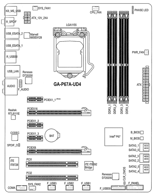
Before we continue on about each part of the motherboard, let’s take a look at the UD4’s block diagram. This diagram shows what each chip controller is for. This should also give us a good idea about how each chip communicates with each other and get a better understanding of the P67 chipset.
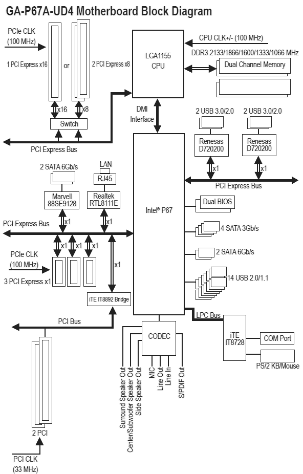
Notice that the 2000MHz is missing from the list of memory supported. Due to CPU behavior, any speed that is not on the list will run at speed that it is closest to (i.e. if your memory is running at 2000MHz, it will be defaulted to 1866 MHz). To our knowledge, this applies to all P67 boards.


The first major controller we see on the motherboard is the ITE IT8728 controller. This controller supports the COM Port if the user gets the optional COM port cable, as well as the PS/2 KB/Mouse ports. The following controllers are the Realtek RTL8111E port for the Gigabit LAN and the Realtek ALC892 audio controller (codec). The ALC892 codec is a Digital to Analogue converter with a 108 dB Signal-to-Noise ratio playback quality. The audio on this motherboard is also Dolby certified, meaning that the overall quality of the audio should be decent.
Moving up the board, we can see the Renesas (NEC Japan) D720200 controller. This is the USB 3.0 Host Controller. There is another Renesas D720200 USB 3.0 Host Controller to the bottom right hand side of the motherboard which we will see in the next few pictures below. We can also see the utilization of high-quality Japanese Capacitors throughout the motheroard.


Next to the Driver MOSFET cooler, we can see a Marvell 88SE9128 controller. This controller is designed to run the two eSATA III ports at the back connectors of the motherboard. Next to the USB connectors, we can also see small fuses. These fuses provide extra power and ensure lower voltage drop for the USB ports. On the second picture we can see the rear ports again which we have already talked about on the previous page.
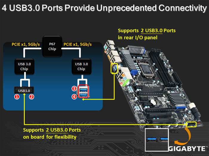
The GIGABYTE P67A-UD7 also has a 3x Power Boost for all the USB ports just like the X58A-UD7 had. This helps tremendously when using USB compatible power-hungry devices which usually require two USB ports to power up, or for charging devices like the iPhone or iPad at a faster rate than on a system that does not have 3x the voltage running through the USB ports. The two top power point slides explain what each chip is exactly responsible for.


Here is a closer look at the expansion slots we’ve seen in previous pictures. We can see that the CMOS battery is located between the PCI-Express slots.
The second picture shows some of the connectors on the motherboard. Starting from the left hand side, the first connector is the optional COM connector that the end-user can get an optional cable for if needed. Right next to the COM connector, we have a SYS_FAN2 PWM 4-pin fan header, and 3 front USB ports. The last USB port supports the On/Off charge feature allowing the user to charge their USB devices even when the PC is off. This USB port can also provide enough power to fully charge an Apple iPad.


Moving further to the bottom right of the UD4, we can see the optional Front USB 3.0 connector which is controlled by the Renesas D720200 controller, and the front panel connectors for the Power and HDD LEDs, Power and Reset switches, and finally the speaker and chassis intrusion headers.
Looking at the motherboard from the right hand side, we can see 4x SATA 2 ports (black) and 2x SATA 3 ports controlled by the P67 chipset.


Here, we can see GIGABYTE’s Patented Dual BIOS. The inclusion of two BIOS chips is a fail-safe measure. In the event of a BIOS failure on one chip, the system will automatically start using the second one so the first one can be reflashed. This will save the user the hassle of an RMA, and can make overclocking more fun and less dangerous. Unfortunately, there is no option to manually switch between the BIOS chips as we could do on the ASUS Rampage III series motherboards. Instead, the system reverts to the second BIOS automatically if it detects a failure in the main BIOS.
On the second picture we see the nicely designed South Bridge (P67 chipset) cooler. Its heatsink design is shaped such that a front fan would have easy air circulation throughout the heatsink for best possible cooling.
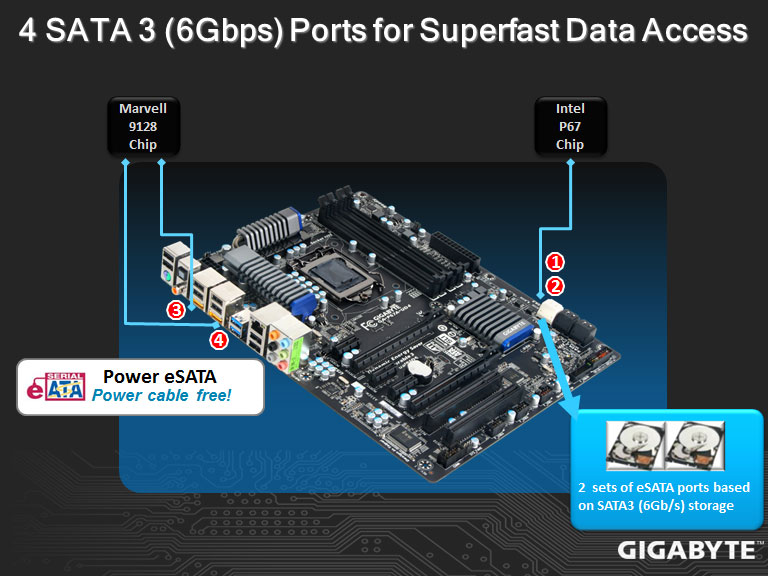
From the diagram above, we can tell that the Marvell 9128 chip controls the rear eSATA III ports, while the Intel P67 chip controls the white SATA III ports.


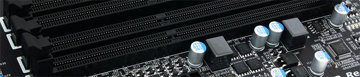
Moving towards the memory slots, we can see a dual power phase design for the memory slots. This will provide for optimal voltage regulation and stable current to the memory modules. We can see a total of 4 DDR3 memory slots. Unfortunately, the P67 motherboards will only have up to 4 memory slots. Depending on the motherboard it could support from 8GBs to 32GBs of DDR3 memory altogether. At this moment we can see that there are no Power and Reset switches provided on the P67A-UD4 motherboard. This is interesting, because most mainstream motherboards would still come with these switches. We cannot see any CMOS reset switches either. It appears that users will have to use the old fashioned method for resetting the CMOS: when system fails to boot, the user needs to turn off the PC, and keep holding the Power Button down the next time the PC is turned on to reset the CMOS. At the top of the motherboard we can also see the PHASE LEDs and the 3-pin PWR_FAN header.


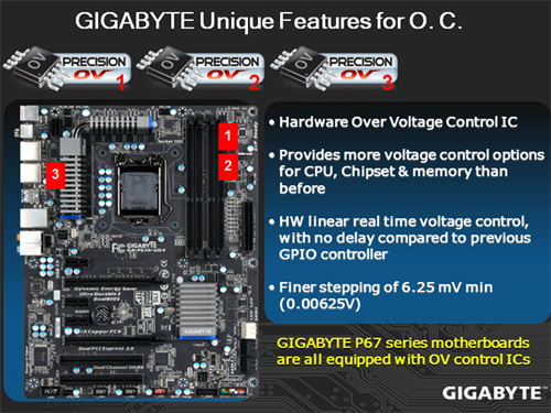
The small chip we see right next to the Driver MOSFET cooler is the VRD12 PWM controller. With the VRD120 controller, higher accuracy is present in V-core control because of the elimination of digitization errors. This is a hardware design, meaning it will not carry the risk of firmware crashes, and it has a greater tolerance to ESD and electrical noise, therefore reducing component damage. Right below the VRD12 chip, we have a PWM 4-pin fan header. On the second picture we see the final 3-pin fan connector and the 8-pin CPU power connector.


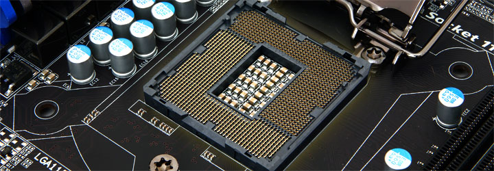
Finally, we can see a very clean design of the 12 phase power that GIGABYTE implemented on this motherboard. This is the perfect amount of phase power for users that are looking into keeping their PCs running at overclocked settings 24/7. These pictures show the LGA1155 socket, which can be paired with the latest Sandy Bridge processors. One bad thing I’ve noticed about the surrounding desing of components around the socket on the GIGABYTE motherboards was the very close capacitors to the socket. With larger coolers that also have larger bases, it can be difficult to properly fit a cooler onto your processor. We are using the Heatkiller Rev 3.0 LGA 1156 waterblock, however it had a very had time fitting properly. The only way we could fit it was by pushing a bit on the capacitors.


Here we have a closer look at the waterblock being installed as well as some new Kingston HyperX H2O memory kits. On the second picture we can see how the capacitors to the left of the waterblock are extermely close and while all of them push on the waterblock, the top one seems to be squished. Thankfully nothing bad happened to the motherboard.
BIOS
Main Page


MB Intelligent Tweaker (M.I.T.)


It is interesting to see that while the BIOS for the GIGABYTE P67A-UD7 does not differ a lot, the sections that have options for different settings usually provide more options for the user. This is why the P67A-UD7 motherboard has more control over the settings in a system. The P67A-UD4 has all the necessary options that most users will require. For instance, the UD4 only has AUTO, Enabled and Disabled options for the Load-Line Calibration, while the UD7 has AUTO, Disable, Level 1, and Level 2 settings. To sum it up, the UD7 is a motherboard where everything can be fine tuned, while the UD4 has is a board for coarser adjustments. The UD4 and UD7 also allow for fine tuning each core’s multiplier, for the processor, especially with Turbo enabled.
Advanced BIOS Features


Integrated Peripherals, Power Management Setup & PC Heath Status


Overclocking

Those that have read our Intel 2600K Processor Review might find this section familiar. It’s actually the same page we used in that review, because even in that review, we used the GIGABYTE P67A-UD4 and UD7 motherboard to overclock our 2600K processor.
Though overclocking is usually reserved for a small fraction of all computer users, it is something that enthusiasts expect, so they can squeeze out extra performance at lower cost. Intel’s Sandy Bridge has once again changed how we overclock a system. The BCLK on the I7 2600K is at 100MHz by standard and can only be tweaked a bit before your system becomes unstable. This is because the PCIE and other computer hardware depend on these numbers. In order to overclock, we can raise the multiplier based on what Intel allows on a given processor.

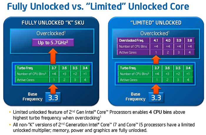
While Intel did not completely forbid any overclocking, it leaves little room for changes, and makes overclocking slightly more challenging for those who purchase non-K series processors with the limited multiplier. Intel does acknowledge the customers who want to push the limits on their CPU, so they are producing the “K” series, like the current Lynnfield with unlocked multiplier. Currently, there are two models: the Core i5 2500K and the Core i7 2600K. Intel priced the “K” models at just $20 higher than the non-K versions, so in terms of price, there is little difference between the two.
For those who have the non-K processor, Intel still offers a bit of overclocking headroom. Users can adjust the power and memory ratio, but the core ratio will be limited. Regardless of which model users choose, they can no longer can push the processor as far as you want because Intel sets an upper limit on the multiplier, which essentially caps the maximum clockspeed.
Overclocking the i7 2600K Processor
Those who really want to overclock their CPUs should pick the K series processor in combination with the P67 chipset. Pairing the two will allow users to increase the core ratio, DDR3 ratio, power and current limit. For those who are using H67 chipset, overclocking will be limited to only the graphics. We do not have the locked processor to test so we do not know how far it can be pushed. However, based on the Intel’s information, it appears that the Core i5 2500 can overclock up to 4.1GHz (41x100MHz) by raising the core ratio, while the 2500K and 2600K can achieve up to 5.7GHz (57x100MHz). This indicates that for locked processors, users can raise the core ratio up to 41x, while the unlocked can go up to 57x. However, each CPU has its own wall for multipliers. There is a 50% chance that a user will reach 4.5GHz speeds without reaching the multiplier wall, while there is a 20% chance for 4.7GHz, and a 10% chance for 4.8GHz to 5.0GHz. Finally, there is about a 2% chance the user will be able to overclock past 5.0GHz.
Intel’s Turbo also factors into overclocking because the processor will throttle to different clockspeeds depending on how many cores are active. The Intel DP67BG motherboard, for example, allows users to adjust each core’s multiplier independently, but we overclocked the processor with all four cores running at the same speed. With the voltages set to default, we were able to overclock the system to 4.8GHz by simply increasing the multiplier to 48x instead of the stock 34x.
We put together a chart that shows the Core i7 2600K processor running with Turbo off and with Hyper-Threading on. We have also left all , options enabled and downclocked when the CPU is at idle mode, but we turned off Intel Thermal Monitoring to prevent the processor from getting downclocked if critical temperatures are reached. However, this should not have affected our performance because we had a very powerful water cooling setup cooling the 2600K, but to get the best possible accurate results, we turned it off anyways.
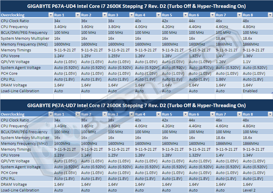
Immediately we can see that our charts stopped at 48x multiplier. This is due to the fact that each processor has its limitation — a wall — that it won’t go past. Though we were able to boot at 49X multiplier, the system would not be stable at all, even with high voltages. Here is an excerpt from an ASUS overclocking guide provided to us about the percentage of processors that overclock to a certain frequency from a total of 100 Sandy Bridge processors:
Results are representative of 100 D2 CPUs that were binned and tested for stability under load; these results will most likely represent retail CPUs.
1. Approximately 50% of CPUs can go up to 4.4-4.5 GHz
2. Approximately 40% of CPUs can go up to 4.6-4.7 GHz
3. Approximately 10% of CPUs can go up to 4.8-5 GHz (50+ multipliers are about 2% of this group)
Additionally it is recommended to keep 「C1E」and「EIST」option enabled for the best overclock scaling. This is different than previous Intel overclocking expectations where the best scaling was with disabled power states or power management options.”
However, by reaching the multiplier wall, the user is still not 100% finished with overclocking. It is still possible to overclock the BCLK as long as the hardware being controlled through the BCLK is not too sensitive to major changes in frequency. Since the BCLK is now controlling not only the CPU frequency, but also the Memory and PCI-E lanes, it is important to understand that there is only a slight change that can be done before the hardware will get unstable, especially PCI-E hardware like RAID cards and Video Cards.
For example, if the user finds the CPU ratio wall to be at 47x, but really wants to achieve 4.9GHz performance, it is still possible to bump up the BCLK to about 104.3 MHz. If we do the math, 47 x 104.3 = 4902 MHz or about 4.9 GHz.
NOTE: The Intel DP67BG motherboard is not able to fine tune the BCLK like other motherboards do, like the GIGABYTE P67A-UD4 or UD7, or even the ASUS P8P67 Pro or Deluxe motherboards. The Intel DP67BG motherboard is limited to whole number BCLK frequencies, including 100, 101, 102, and so on.
The first two pictures show the stock 2600K and it’s temperatures and settings. These were run on the Intel DP67BG motherboard.


Click Image For a Larger One
The following tests were done with the Intel stock tower cooler that we examined at on the previous page. The fan was on maximum speed, and the CPU reached a maximum of 61C during full load. When the tower cooler’s fan is decreased to automatic fan control by the BIOS, the CPU gets around 66C during full load. These are fantastic temperatures at these frequencies and with the tower cooler on automatic, we could barely hear the fan on the cooler. On maximum fan speed, the tower cooler has great airflow, but most of the air was just being blown around the motherboard rather than through the heatsink. This provides for excellent cooling for the memory and motherboard VRM, but can get quite annoying.
Lets take a look at the performance we were able to achieve with the Intel Core i7 2600K Sandy Bridge processor, and what temperatures were reached at certain voltages. The charts provided above show the voltages and settings used during each test. The screenshots below show the GIGABYTE P67A-UD7 motherboard used to overclock the 2600K processor. Unfortunately, CPU-Z does not have a clear voltage reading from the GIGABYTE P67A-UD7 motherboard at the moment, so the VCore or Core Voltage is reported as 1.044V.
The temperatue of theprocessor stays the same regardless of the motherboard, but for accurate P67A-UD4 settings during overclocking, please reffer to the top charts. Both the UD4 and the UD7 were stable at the settings provided in those charts.


Click Image For a Larger One
These are the results to the maximum frequencies we were able to achieve with the Core i7 2600K processor. According to the tests, temperatures were not a problem in reaching the limit of our processor. The actual limit we reached was the 48x multiplier wall. We noticed that in the LinX test, even without lowering the clockspeed, when we lowered the voltage, the performance dropped a bit, though it is not certain that it will happen every time. While both benchmarks were stable after several hours of stress testing the CPU and Memory, the top stress test was done at a VCore of 1.340V and with VDroop on at Level 2. The bottom benchmark was performed with a VCore of 1.315V and with VDroop at Level 2 settings. We can see that between 1.315V and 1.340V, there was a 2 degree temperature difference. It is still amazing to see a maximum temperature of 67C while running fully stable at 4.8 GHz. However, notice that the Core #0 temperature is around 57C while the Core #2 temperature is at 67C. We believe this is because of the incompatibility of the waterblock with the GIGABYTE P67A-UD4 and P67A-UD7 motherboards. Those motherboards have some capacitors very close to the socket, which obstructed the waterblock we used (Heatkiller Rev 3.0 LGA 1156 socket waterblock). The problem was that when we installed the waterblock on the CPU, the whole waterblock would not fully contact the CPU, because the capacitors on the left hand side of the socket would push the waterblock slightly higher up. It could also be that the thermal paste was not perfectly spread throughout the installation process, so while we got 67C at full load, it may be possible for other users to reach much lower temperatures when they use a fully compatible CPU waterblock or CPU Air Cooler.
NOTE: Our water cooling loop is extremely quiet and does not get louder as load increasees. We are running 3 fans that cool our radiators at 1400RPM, and the noise from the fans are completely inaudible at around half a meter away from the system. It would be difficult to reach such temperatures at low acoustic levels with air coolers. Our gratitude to AcousticPC.com for providing us with several parts to our complete water cooling loop.
Temperatures

The temperatures were recorded with CoreTemp while running LinX for a few hours during stability tests and double checking the results with OCCT for 20 minutes right after LinX finished its stress test. The processor was fully overclocked. The results were recorded carefully. After the results were recorded, we waited for 30 minutes before taking Idle temperature measurements. The results were as follows:
| Motherboard | Temperature (Idle / Load) |
|---|---|
| ASUS P8P67 Pro |
N/A / 36C |
| ASUS P8P67 Deluxe |
N/A / 37C |
| GIGABYTE P67A-UD4 |
38C / 40C |
| GIGABYTE P67A-UD7 |
41C / 43C |
We can see higher temperatures on the GIGABYTE motherboards than on the ASUS motherboards. It is possible that the ASUS motherboard has a a better heatsink design than the GIGABYTE boards, but nontheless, both motherboards are within perfect temperature ranges, and they report extremely low load temperatures. The UD7 seems to have higher temperatures, but this is understandable because it is also equipped with the Nvidia NF200 chip, which adds to the amount of heat dissipated by the onboard heatsinks.
Power Consumption

The power consumption was tested while running LinX for a few minutes at stock settings. The results were recorded carefully with a Kill-A-Watt power consumption measuring tool at the wall. After the results were recorded, we waited for yet another few minutes minutes before taking Idle power consumption measurements.
| Motherboard | Power Consumption (Idle / Load) |
|---|---|
| GIGABYTE P67A-UD4 |
189W / 255W |
| GIGABYTE P67A-UD7 |
195W / 265W |
Just as the temperatures were a tad higher on the UD7 than on the UD4, we can see the same characteristic of the boards in power consumption. The UD4 was able to pull in about 10W lower at full load than the UD7. We believe the reason for this is the added features and chipsets, including the T.I. IEEE 1394a FireWire Controller, extra USB 3.0 controllers and the NF200 chipset for 3-Way SLI support.
Testing & Methodology
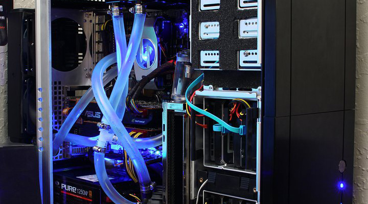
(Water Cooling setup provided by AcousticPC.com)
We’ve expanded our testing suite considerably for the P67 chipset, and will continue to use the same methods for most of the motherboards and CPU’s we test. In the interests of thoroughness and accurate results, we run each test at least three times, and some tests more than that. We average the total of all the tests from each benchmark then report the average here.
The OS we use is Windows 7 Pro 64bit with all patches and updates applied. We also use the latest drivers available for the motherboard and any devices attached to the computer. We do not disable background tasks or tweak the OS or system in any way. We turn off drive indexing and daily defragging. We also turn off Prefetch and Superfetch. This is not an attempt to produce bigger benchmark numbers. Drive indexing and defragging can interfere with testing and produce confusing numbers. If a test were to be run while a drive was being indexed or defragged, and then the same test was later run when these processes were off, the two results would be contradictory and erroneous. As we cannot control when defragging and indexing occur precisely enough to guarantee that they won’t interfere with testing, we opt to disable the features entirely.
Prefetch tries to predict what users will load the next time they boot the machine by caching the relevant files and storing them for later use. We want to learn how the program runs without any of the files being cached, and we disable it so that each test run we do not have to clear pre-fetch to get accurate numbers. Lastly we disable Superfetch. Superfetch loads often-used programs into the memory. It is one of the reasons that Windows Vista occupies so much memory. Vista fills the memory in an attempt to predict what users will load. Having one test run with files cached, and another test run with the files un-cached would result in inaccurate numbers. Again, since we can’t control its timings so precisely, it we turn it off. Because these four features can potentially interfere with benchmarking, and and are out of our control, we disable them. We do not disable anything else.
Test Rig
| Test Rig | |
| Case | Silverstone Temjin TJ10 |
| CPU |
Intel Core i7 2600K @ 4.8 GHz |
| Motherboard |
Intel DP67BG LGA 1155 Motherboard GIGABYTE P67A-UD4 GIGABYTE P67A-UD7 |
| Ram |
Kingston HyperX H20 2133 MHz Dual-Chanel 8GB (4x2GB) Kit |
| CPU Cooler |
Heatblocker Rev 3.0 LGA 1156 CPU Waterblock Thermochill 240 Radiator |
| Hard Drives |
4x Seagate Cheetah 600GB 10K 6Gb/s Hard Drives 2x Western Digital RE3 1TB 7200RPM 3Gb/s Hard Drives |
| SSD | 1x Zalman SSD0128N1 128GB SandForce SSD |
| Optical | ASUS DVD-Burner |
| GPU |
ASUS ENGTX580 Voltage Tweak |
| Case Fans |
1x Quiet Zalman Shark’s Fin ZM-SF3 120mm Fan – Top 1x Silverstone 120mm fan – Front 1x Quiet Zalman ZM-F3 FDB 120mm Fan – Hard Drive Compartment |
| Additional Cards |
LSI 3ware SATA + SAS 9750-8i 6Gb/s RAID Card |
| PSU |
Sapphire PURE 1250W Modular Power Supply |
| Mouse | Razer Mamba |
| Keyboard | Logitech G15 |
Test Suite
We will use the following applications to test the performance of the CPU. Benchmarks
| Benchmarks |
|---|
| PcMark Vantage |
| SYSmark 2007 |
| Intel HDxPRT |
| SiSoft Sandra 2011 |
| Cinebench R10 |
| Cinebench R11.5 |
| 3DMark 11 |
| 3DMark Vantage |
| Unigine Heaven Benchmark |
| Crysis Warhead |
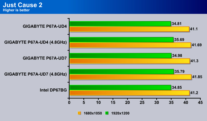
| Just Cause 2 |
Sisoft Sandra 2011b
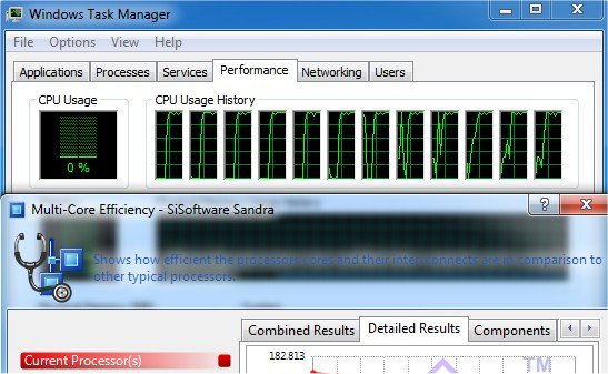
“SiSoftware Sandra (the System Analyzer, Diagnostic and Reporting Assistant) is an information & diagnostic utility. It should provide most of the information (including undocumented) you need to know about your hardware, software and other devices whether hardware or software. It works along the lines of other Windows utilities, however it tries to go beyond them and show you more of what’s really going on. Giving the user the ability to draw comparisons at both a high and low-level. You can get information about the CPU, chipset, video adapter, ports, printers, sound card, memory, network, Windows internals, AGP, PCI, PCI-X, PCIe (PCI Express), database, USB, USB2, 1394/Firewire, etc.”
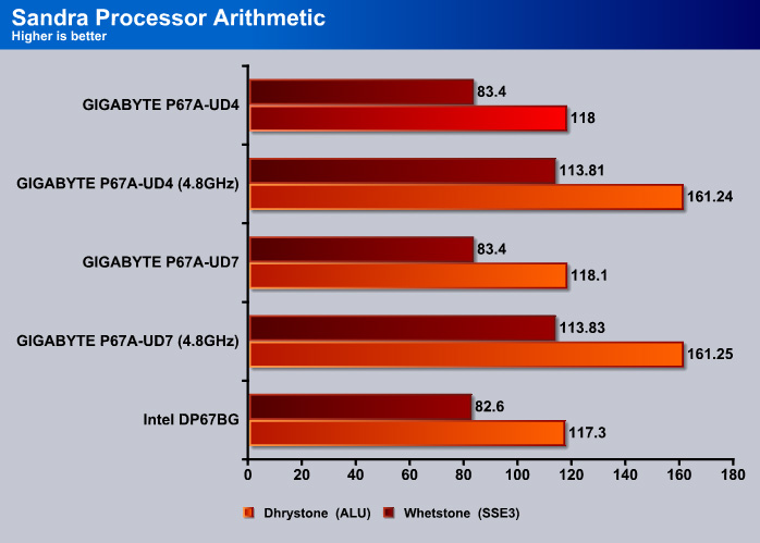
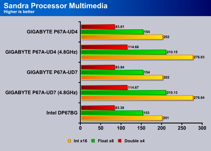

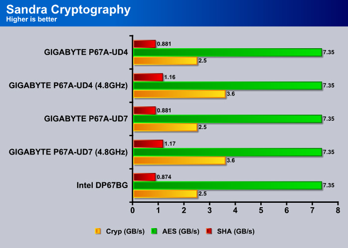
The results are essentially identical for the UD4 and UD7. Compared to the Intel board, the GIGABYTE board offers a slightly higher performance throughout the Sandra tests.
Cinebench R10 and R11.5
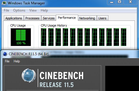
“CINEBENCH is a real-world test suite that assesses your computer’s performance capabilities. MAXON CINEBENCH is based on MAXON’s award-winning animation software, CINEMA 4D, which is used extensively by studios and production houses worldwide for 3D content creation. MAXON software has been used in blockbuster movies such as Spider-Man, Star Wars, The Chronicles of Narnia and many more. MAXON CINEBENCH runs several tests on your computer to measure the performance of the main processor and the graphics card under real world circumstances. The benchmark application makes use of up to 16 CPUs or CPU cores and is available for Windows (32-bit and 64-Bit) and Macintosh (PPC and Intel-based). The resulting values among different operating systems are 100% comparable and therefore very useful with regard to purchasing decision-making. It can also be used as a marketing tool for hardware vendors or simply to compare hardware among colleagues or friends.”
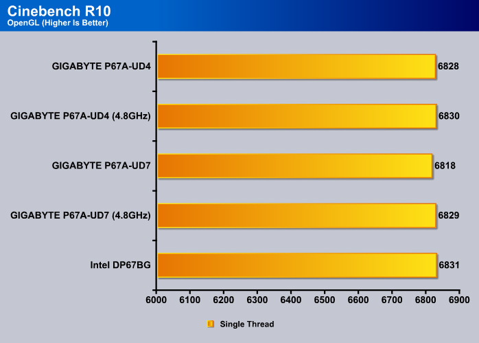
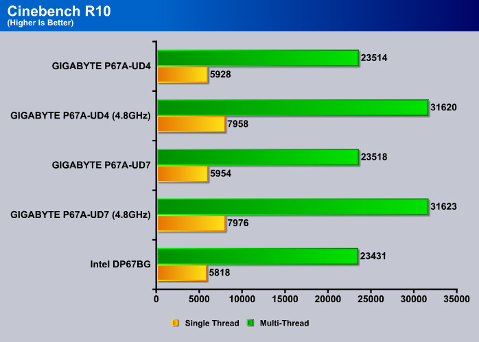

All three boards scored identical points in the Cinebench R11.50 test.
PCMark Vantage
PCMark Vantage is the latest system benchmark tool from Futuremark. The benchmark consists of tests such as application launches, file searches, web browsing, video playback, photo editing, and gaming.
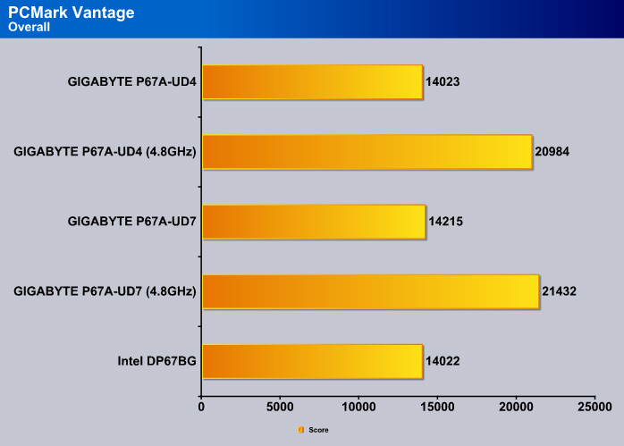
All three boards perform identical at the stock speed.
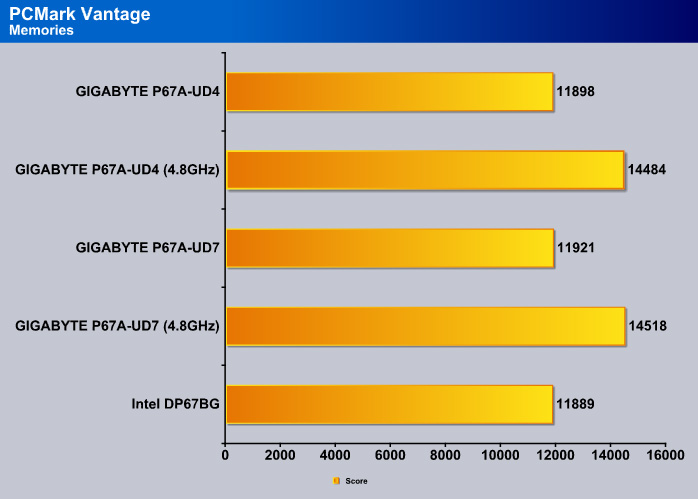
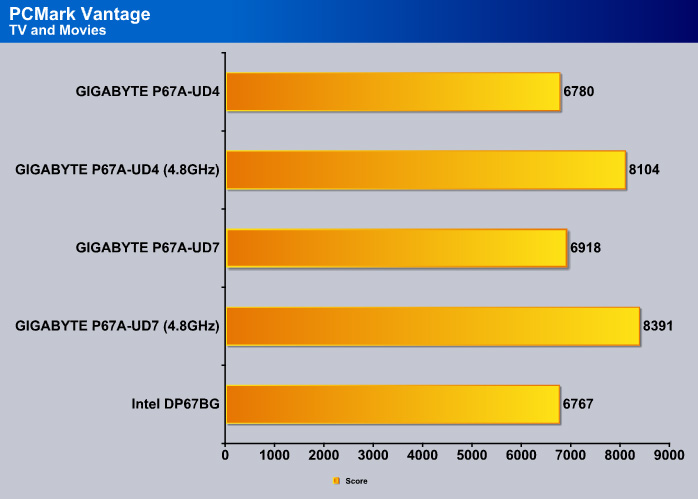
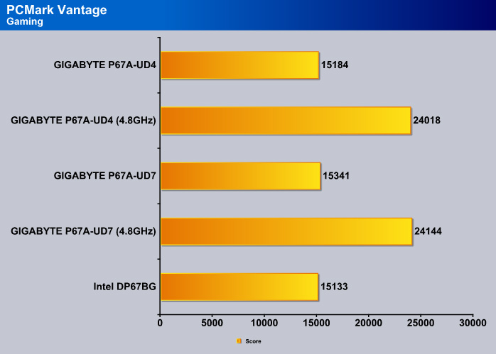

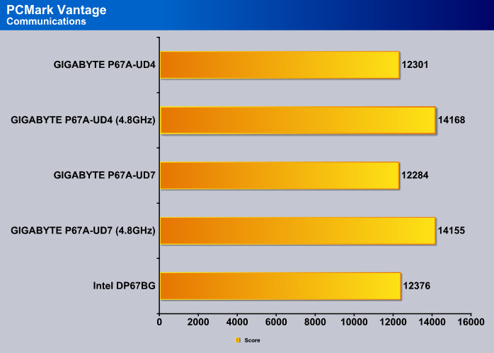
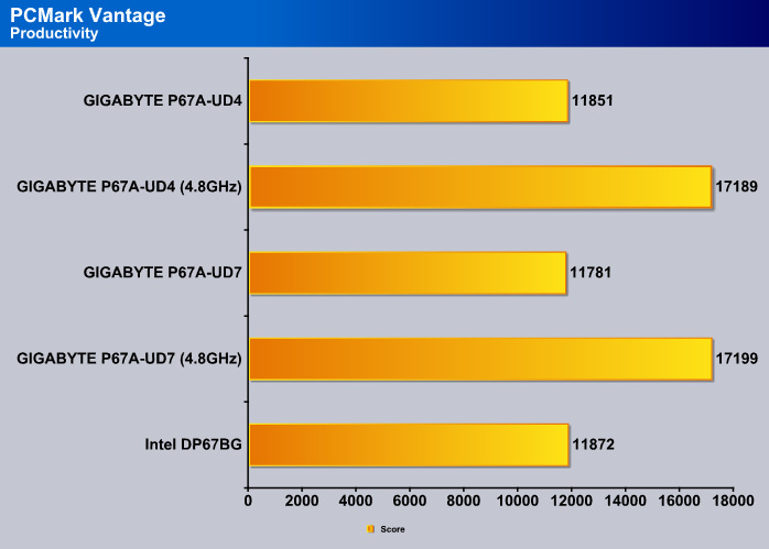
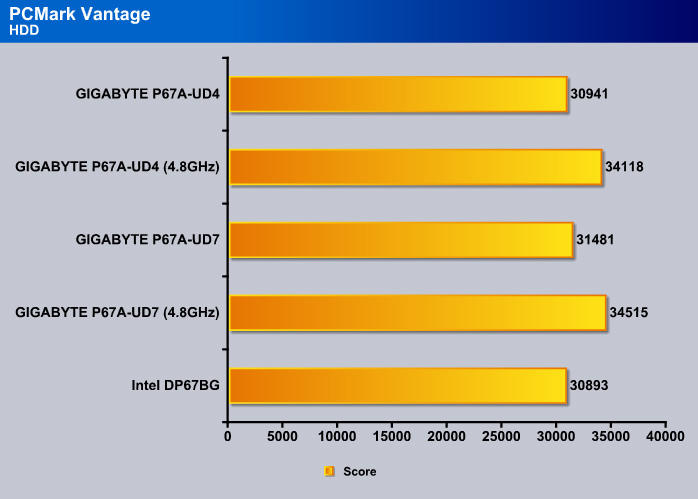
It would be impossible to tell the boards apart solely based on the scores because all three boards eseentially yield identical scores.
INTEL HDXPRT
Intel HDxPRT is a collection of real-life applications that test processor’s power at transcoding digital multimedia contents to and from various sources. This is one of the tests that allows us to see a glimpse of Sandy Bridge’s real-world performance. For the detail on what each test consists of, see Intel’s HDxPRT whitepaper.
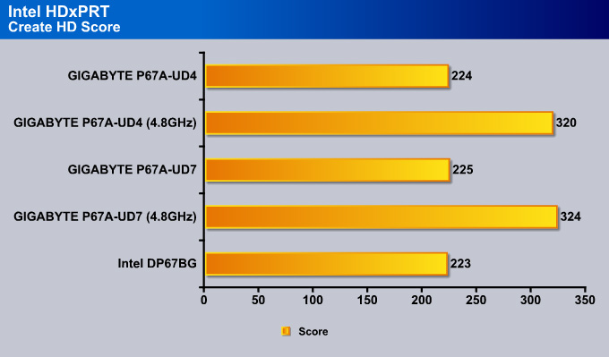
The UD7 scored 2 points higher than the Intel board and 1 point higher than the UD4.
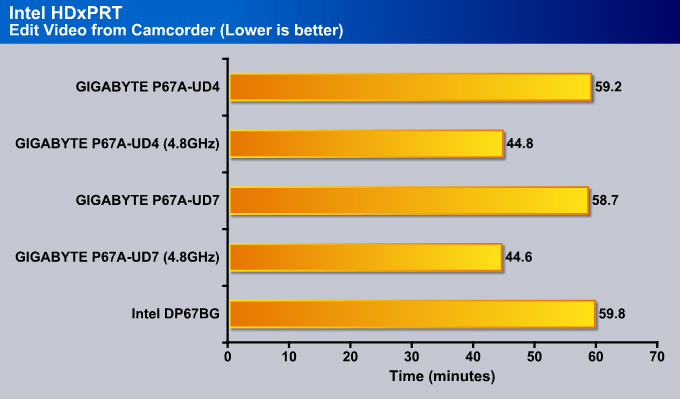
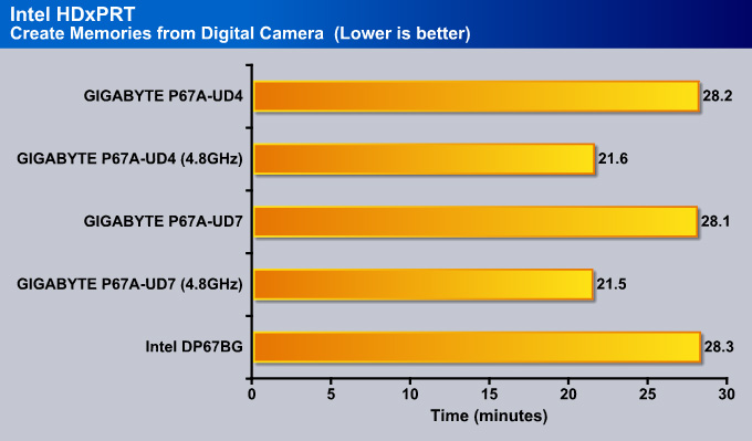
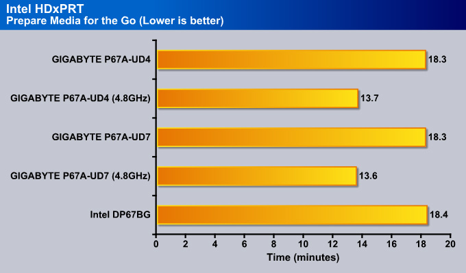
Practically, the difference between the three boards is only 0.1 minutes, nothing major.
SysMark 2007 Preview
SYSMark 2007 Preview is a tool developed by Bapco that supports both 32bit and 64bit Windows XP, Vista, and 7. The benchmark is application-based, reflecting the usage pattern of the common desktop user. The benchmark focuses in four areas: E-learning, 3D, Productivity, and Video Creation. While the test is designed primarily for testing processors, it can also be used to reflect hard drive performance in real-life scenarios. This gives us a great idea on how the processor performs under these CPU intensive applications.
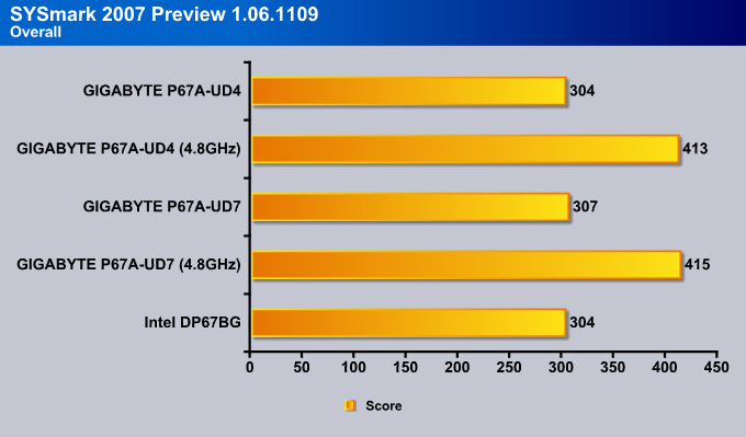
SYSMark 2007 is a real-life benchmark so it gives an idea of the performance of the boards in real-life situations. Here the UD4 scored the same points as the Intel board, and the UD7 came in at 3 points higher.
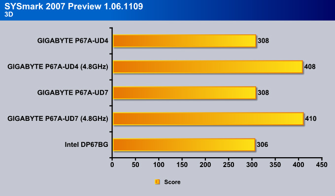
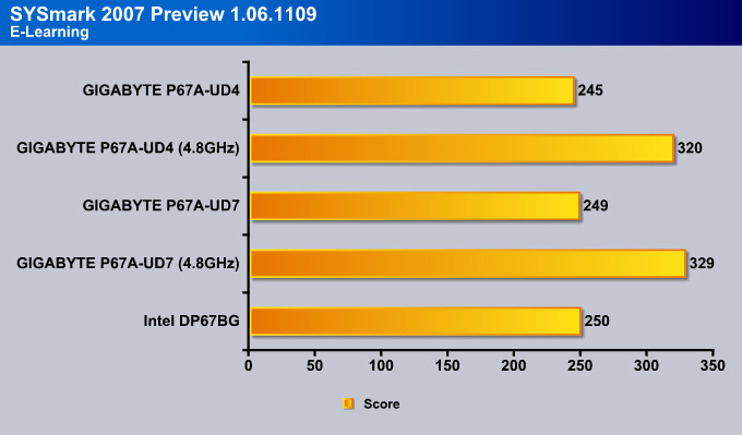

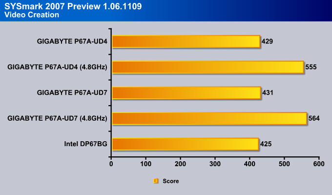
In the individual test, the trend continued, with the UD7 coming in just a couple of points ahead of the UD4. However, the difference between the UD4 and UD7 seems to be widen with our overclocked CPU.
3DMark Vantage

For complete information on 3DMark Vantage Please follow this Link:
www.futuremark.com/benchmarks/3dmarkvantage/features/
The newest video benchmark from the gang at Futuremark. This utility is still a synthetic benchmark, but one that more closely reflects real world gaming performance. While it is not a perfect replacement for actual game benchmarks, it has its uses. We tested our cards at the ‘Performance’ setting.

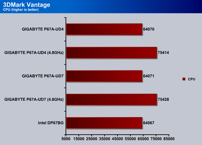
The CPU score is what we expected, the 4.8GHz overclocked CPU yields 11344 more points.

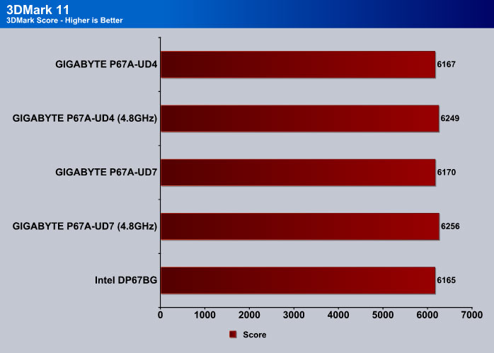
3DMark 11
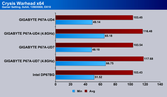
Crysis warhead

Crysis Warhead is the much anticipated standalone expansion to Crysis, featuring an updated CryENGINE™ 2 with better optimization. It was one of the most anticipated titles of 2008.
We ran Warhead using gamer’s setting at resolution of 1280×1024 and DirectX 10. We tested both no AA an 2x AA.
Just Cause 2

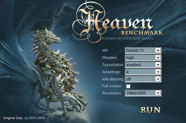
Unigine Heaven 2.1

Unigine Heaven is a benchmark program based on Unigine Corp’s latest engine, Unigine. The engine features DirectX 11, Hardware tessellation, DirectCompute, and Shader Model 5.0. All of these new technologies combined with the ability to run each card through the same exact test means this benchmark should be in our arsenal for a long time.
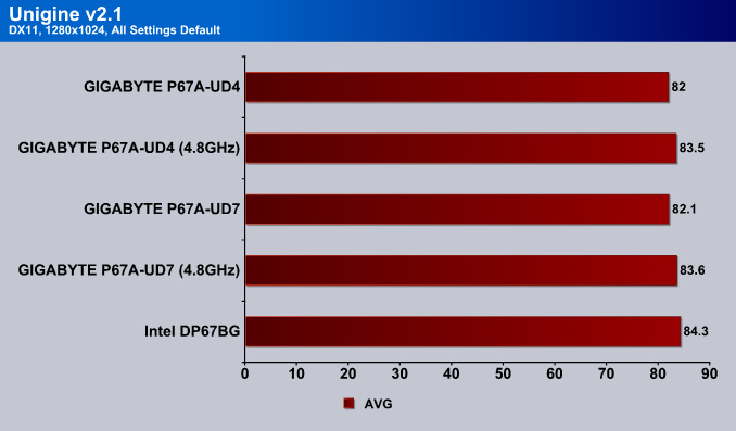
In games, was tested at a low resoultion while keeping the gamer preset settings to see if users running lower resoultions will have a performance increase in gaming. As what we saw with other benchmarks, the UD7 has a narrow lead with overclocked processor but at stock, the two boards are pretty much identical. One surprise here is that the Intel board scored higher than the Gigabyte boards in Unigine v2.1 and Just Cause 2. Once again, the differences are so small that they could easily change if we ran reran the test so all three boards were essentially identical in terms of gaming performance.
Final Thoughts
The GIGABYTE P67A-UD4 motherboard has about the same amount of performance as any other motherboard on the market right now, but what matters the most are its features and whether they will be enough for an average user. The overall motherboard has a very clean and high-quality design just like the GIGABYTE P67A-UD7 did, though we were dissapointed with the push-pin design heatsinks on this motherboard. It would have been a much sturdier design if the motherboard had screws instead of pushpin design heatsinks. How much extra would have 6 more screws cost? Probably not even $2.
GIGABYTE recently updated their BIOS on their latest P67 paltform motherboards to have full support for their EFI code. While it is still not a UEFI BIOS, with EFI, the user can run higher capacity single partition hard drives , like the latest 3TB drives that were recently announced (2TB limit in the past). GIGABYTE also explained that their EFI code is backwards compatible with their X58 chipset motherboards as well.
While overclocking for GIGABYTE motherboards seems to be a clear marketing scheme, we must agree that these boards are always a snap to work with, and we believe that this motherboard is an excellent choice for even an everyday average and high-end user. While the UD3P/R might be a great option as well, the UD4 seems to be the sweet spot for great overall specifications and features. However, we do believe that GIGABYTE should have included an IEEE 1394 port on the P67A-UD4 to really make this motherboard the best choice for all types of users, and a board that would have stood out from the crowd for it’s MSRP price of $199.99.
Reviewer’s Opinion:
If you need a motherboard that will provide excellent stability, quality, high performance, and overall nice collection of features, the P67A-UD4 will be a great choice. If you are a video editor, and you need at least one FireWire (IEEE 1394) port, then the P67A-UD5 will be the motherboard for you. But if you know for a fact that you will not need two PCI-Express x16 and x8 slots, and would like to stay on the budget side, then the GA-P67A-UD3R would still be a nice option with up to 2 USB 3.0 ports and 2 SATA 3 ports.
On the other hand, the ASUS P8P67 Pro motherboard might be an excellent choice as well, because it comes with almost the same specifications that the GIGABYTE P67A-UD4 comes with, except it also has a FireWire and a bluetooth antenna to communicate with your bluetooth powered devices. The ASUS P8P67 motherboards also comes with front panel USB 3.0 adapter, as well as an upgraded UEFI BIOS support. Please check out the P8P67 Pro and Deluxe reviews here.
Finally, if you need the top of the line performance in 3-Way SLI or 3-way CrossFireX configuration as well as beastly overclocking performance for the processor, while also having lots of USB 3.0 and SATA III slots, the GIGAYBTE P67A-UD7 or the ASUS Maximus IV Extreme might be your best pick.
Editor’s Opinion:
As I said in the preview, I like this board a lot. I’ve gotten to see it personally, and it looks great. More importantly, however, it provides an opportunity to upgrade. I’ve been stuck with a Core 2 Duo for many years now, and I always wanted to upgrade. I never considered it because the introduction of a new socket every year is tough on the pocketbook (the LGA 775 is a rare exception). But with the P67A-UD4, those who want great hardware can get it without having to spend a fortune on features they don’t need.
Having seen so many P67 boards now, I am torn as to which one to buy, but the UD4 is definitely on my short list. The inclusion of several useful features for consumers and the reduction of features that only the most extreme overclockers require make this a great product for most end-users. I am a bit disappointed that the board’s SATA ports have been cut down, though. Nonetheless, this is a great board, and I might buy it myself.
| OUR VERDICT: GIGABYTE P67A-UD4 Motherboard | ||||||||||||||||||
|
||||||||||||||||||
| Summary: It is worth mentioning that the GIGABYTE GA-P67A-UD4 motherboard is a motherboard that an average computer user looking into upgrading to Sandy Bridge socket LGA1155 processors would be extremely happy to have. Overall its design and performance is top-notch, but it’s lacking a bit in features and accessories, and therefore the P67A-UD4 will receive a 7.5 out of 10 points and the Bjorn3D Bronze Bear Award. |